background image

27


EN 

2

24 

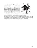
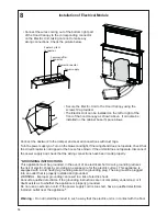
Inserting the Hood Canopy into the support surface from below 


•  Insert the Hood Canopy from below into the 

support worktop, drilled as described above. 

•  With the aid of a support, lift the Hood Cano-

py until the front comes out of the Worktop. 


•  Insert the Brackets 

7.2

, as indicated in the 

figure, into the slots provided and fix them 

with the screws 

12a 

provided. 

•  Centre the Hood Canopy with respect to the 

Cooking Hob slot. 


•  Using the 2 screws 

12c

 provided, fix the 

Hood Canopy to the worktop and remove 

the supports. 


Warning: 

If the cooker top is made from a material that does not allow the screws 

12c

 to be inserted, use 

a small amount of silicone to glue the Brackets 

7.2

 to the top and allow it to dry completely 

before proceeding with installation. 

1

2

L'écart minimum entre l'ouverture pour la surface de cuisson et l'ouverture pour la hotte doit être d'au

moins 1 

3/16

" - 1 

15/16

", selon la résistance du matériau du plan de travail.

• Insérez le cadre de la hotte dans l'ouverture pratiquée dans 

le comptoir par le dessous, de la façon décrite ci-dessus.

Notice d'installation

Dimensions de l'ouverture


EN 

2

23 

INSTALLATION


This Hood is set up to be fitted inside the kitchen unit in: 

• 

Ducting version:

 Evacuation to the outside. 


Sequence of operations - Installation 

•  Drilling the Support Surface and Fitting the Hood 

•  Connections 

•  Functional Check 

•  Disposal of Packaging 


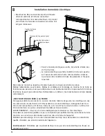
Drilling the Support Surface 


X

812


Warning 

Once the Support surface has been drilled the Hood Canopy can be installed in two ways: 

•  By inserting the Hood Canopy from below ( 

X

 = 106 mm ). 

•  By inserting the Hood Canopy from above ( 

X

 = 113 mm ). 


IMPORTANT 

The minimum distance between the opening for the hob and the one for the hood must be of at 

least 3-5 cm according to the strength of the material used for the working top. 

Y

X

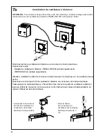
Insertion du cadre de la hotte dans le comptoir par le dessous

• Comme indiqué dans la 

figure, insérez les brides 

7.2 dans les fentes prévues 

et fixez-les à l'aide des vis 

12a fournies.

• Centrez le cadre de la hotte 

par rapport à l'ouverture de 

la surface de cuisson.

• À l'aide des 2 vis 12c fournies, fixez le cadre de 

la hotte au comptoir, puis retirez les soutiens.

Avertissement :

Si le matériau du comptoir ne permet pas la pose des vis 12c, utilisez une petite quantité de 

silicone pour coller les brides 7.2 au comptoir, et laissez-la sécher complètement avant de 

poursuivre l'installation.

• Avec l'aide d'un soutien, soulevez 

le cadre de la hotte jusqu'à ce que 

l'avant ressorte du comptoir.

POUR VOTRE SÉCURITÉ :

AVERTISSEMENT Avant de procéder à l'installation, coupez l'alimentation au niveau du panneau 

électrique et verrouillez-le pour vous assurer que l'électricité n'est pas rétablie accidentellement. S'il 

n'est pas possible de verrouiller le dispositif d'interruption de l'alimentation, affichez de façon ferme 

et bien visible un avis de danger, par exemple à l'aide d'une étiquette sur le panneau.

Hotte

X

Y

30"

25 

15/16

"

4 5/16"

36"

31 

15/16

"  4 5/16"

Summary of Contents for Scirocco Lux 30 BK

Page 1: ...SCLX3015BKNB B SCLX3615BKNB B SCLX3015SSNB B SCLX3615SSNB B Installation Instructions Use and Care Information Instructions d installation Utilisez et d entretien SCIROCCO LUX...

Page 2: ...with your back to an exit Based on Kitchen Firesafety Tips published by NFPA WARNING TO REDUCE THE RISK OF FIRE OR ELECTRIC SHOCK do not use this fan with any solid state speed control device WARNING...

Page 3: ...talled to minimize backward cold air flow and a nonmetallic thermal break should be installed to minimize conduction of outside temperatures as part of the vent system The damper should be on the cold...

Page 4: ...or grounding circuit could result in electrical shock Check with a qualified electrician if you are in doubt as to whether the rangehood is properly grounded Failure to follow electrical requirements...

Page 5: ...5 RANGEHOOD DIMENSIONS 3 11 16 25 1 4 31 1 4 4 3 4 3 16 16 27 7 16 1 4 4 9 13 16 13 1 16 25 9 16 31 9 16 13 1 16 30 36...

Page 6: ...16 Screws 1 8 x 3 8 12b 6 Screws 3 16 x 5 16 12c 8 Screws 3 16 x 9 16 Qty Documentation 1 Instruction Manual 10 duct collar used with Remote Blowers Available Accessories Purchased separately Recircul...

Page 7: ...tions Functional Check Disposal of Packaging Drilling the Support Surface X 812 Warning Once the Support surface has been drilled the Hood Canopy can be installed in two ways By inserting the Hood Can...

Page 8: ...e figure into the slots provided and fix them with the screws 12a provided Insert the Hood Canopy into the cooker top drilled as described above Centre the Hood Canopy with respect to the Cooking Hob...

Page 9: ...to the Hood Canopy using the screws 12b provided without tightening completely Using the screws 12c provided fasten the other part of the brackets 7 3 either to the side walls of the unit or to the l...

Page 10: ...e plug is properly positioned The Internal Blower can be rotated as shown in the figure 2 for multiple venting directions Screw the Internal Blower to the Hood Canopy using the screws 12a and 12b prov...

Page 11: ...11 Connect the Wire Connector from the Blower with the correct connector on the Electric Unit Secure the Wire Connector from the Blower at the Electric Unit with 2 screws 3...

Page 12: ...ector to the connector of the Electric Unit Run 2 wire plus ground power cable from the Remote Blower to wiring box on the Cover according to local codes and ordinances Use Listed fittings Installatio...

Page 13: ...the Black lead of the rangehood B with a twist on type wire connector C Connect the Green E Green and Yellow ground wire under the Green grounding screws Replace the field wiring compartment cover Co...

Page 14: ...must be grounded In the event of an electrical short circuit grounding reduces the risk of electric shock by providing an escape wire for the electric current This appliance is equipped with a cord ha...

Page 15: ...t pipe select the version that applies et lect the ver break the ange 2 using 1 1 2 2 30mm 1 3 16 Standard Outlets According to your venting direction Front or Rear break off the outlet hole already m...

Page 16: ...o return the mobile canopy to the Standard position 9 Installation of Top Frame Raise the downdraft to the Upper Position by a 1 2 See Page 15 for Use of Controls Remove the sponge guards from the cor...

Page 17: ...ning If the downdraft remains partially open for any reason press the Button to complete the opening or closing cycle USE Control panel Button Function o t t u b D E L n A The button only works when t...

Page 18: ...sed for 2 Seconds Closes the downdraft and Motor Lights Off Only with downdraftUp Decreases the working speed each time it is pressed Only with downdraft Up Increases the working speed each time it is...

Page 19: ...her and need to be cleaned whenever button B lights up or atleastonceevery2monthsuse ormorefrequently if use is particularly intensive Resetting the alarm signal Turn the Lights and the Motor off Pres...

Page 20: ...20 Wiring Diagram...

Page 21: ...om accident alteration misuse abuse fire flood acts of God improper installation installation not in accordance with electrical or plumbing codes or Faber documentation or use of products not approved...

Page 22: ...j t appel s 4 Unevoiedesortiesetrouvederri revouspendantquevous teignezlesflammes D apr sleguide KitchenFiresafetyTips publi parlaNFPAaux tats Unis AVERTISSEMENT POURR DUIRELERISQUED INCENDIEOUDECHOC...

Page 23: ...hermique La barri re thermique doit tre positionn e le plus pr s que possible de l endroit o le syst me de ventilation p n tre dans la partie chauff e de la maison CRIT RES DE VENTILATION D terminezqu...

Page 24: ...sible dans le circuit neutre ou de mise la terre peut entra ner un choc lectrique Consultez un lectricien qualifi si vous n tes pas certain de la mise la terre de la hotte Le non respect des exigences...

Page 25: ...25 DIMENSIONS DE LA HOTTE 3 11 16 25 1 4 31 1 4 4 3 4 3 16 16 27 7 16 1 4 4 9 13 16 13 1 16 25 9 16 31 9 16 13 1 16 30 36...

Page 26: ...s1 8 x3 8 12b 6 Vis3 16 x5 16 12c 8 Vis3 16 x9 16 Qt Documentation 1 Moded emploi Collierdeconduit10 utilis avecventilateurs distance 5 12b 12b Accessoires disponibles Achet S par ment Trousse de recy...

Page 27: ...kaging Drilling the Support Surface X 812 Warning Once the Support surface has been drilled the Hood Canopy can be installed in two ways By inserting the Hood Canopy from below X 106 mm By inserting t...

Page 28: ...as indicated in the figure into the slots provided and fix them with the screws 12a provided Insert the Hood Canopy into the cooker top drilled as described above Centre the Hood Canopy with respect t...

Page 29: ...les brides 7 3 au cadre de la hotte l aide des vis 12b fournies sans les serrer fond Utilisez les vis 12c fournies serrez l autre partie des brides 7 3 soit au mur c t de l appareil ou la partie inf...

Page 30: ...ne position ad quate Le ventilateur interne peut tre tourn comme illustr la figure 2 pour diverses directions de ventilation Vissez le ventilateur interne au cadre de la hotte l aide des vis 12a et 12...

Page 31: ...31 Connectez le connecteur des fils du ventilateur au connecteur du module lectrique correspondant Fixez le bo tier de connecteur du ventilateur sur le module lectrique l aide de 2 vis 3...

Page 32: ...ble lectrique 2 fils et fil de mise la terre partir du ventilateur distance jusqu au bo tier de connexion sur le couvercle conform ment aux codes et r glementations en vigueur Utilisez les raccords i...

Page 33: ...e d un connecteur verrouill par rotation C Branchez le fil vert E vert et jaune de mise la terre sous les vis de mise la terre vertes Remettez en place le couvercle du compartiment des c blages extern...

Page 34: ...ise la terre r duit le risque de choc lectrique en cas de court circuit car elle fournit un fil d vacuation au courant lectrique Cet appareil est muni d un cordon pr sentant un fil de mise la terre av...

Page 35: ...lectionnez la version appropri e et lect the ver break the ange 2 using 1 1 2 2 30mm 1 3 16 Sorties standard Selon la direction de ventilation avant ou arri re d foncez l orifice de sortie d j marqu e...

Page 36: ...la position lev e consultez la page 15 pour en savoir plus sur l utilisation des commandes Retirez les protections en ponge sur les coins du verre Prenez le cache sup rieur et ins rez le partir du des...

Page 37: ...tes la fin de ce d lai le syst me retourne la vitesse pr c demment r gl e Pour la d sactiver appuyer sur cette m me touche couper le moteur ou fermer la porte Touche led clignotante D Fonctionne seule...

Page 38: ...working speed each time it is pressed Only with downdraft Up Increases the working speed each time it is pressed Intensive Only with downdraft Up Activates the Intensive function Delay Only with downd...

Page 39: ...nt tre nettoy s lorsque le bouton B s allume ou au moins une fois tous les 2 mois d usage ou encore plus fr quemment en cas d utilisation particuli rement intensive R initialisation du signal d alarme...

Page 40: ...40 Sch ma de c blage...

Page 41: ...es d coulant d un accident d une modification de l utilisation incorrecte ou abusive d un incendie d une inondation d un cas de force majeure d une installation inad quate d une installation non confo...

Page 42: ......

Page 43: ......

Page 44: ...991 0476 868_04 180626 D003300_03...

Reviews: