background image


EN 


2


Instructions Manual 
INDEX


RECOMMENDATIONS AND SUGGESTIONS ......................................................................................................................4 
CHARACTERISTICS..............................................................................................................................................................5 
INSTALLATION ......................................................................................................................................................................7 
USE.......................................................................................................................................................................................11 
MAINTENANCE....................................................................................................................................................................12 

Summary of Contents for Stilo Isola

Page 1: ...Stilo Isola...

Page 2: ...EN 2 2 Instructions Manual INDEX RECOMMENDATIONS AND SUGGESTIONS 4 CHARACTERISTICS 5 INSTALLATION 7 USE 11 MAINTENANCE 12...

Page 3: ...JP 3 3 15 16 18 22 23...

Page 4: ...ust gas The kitchen must have an opening communicating directly with the open air in order to guarantee the entry of clean air USE The extractor hood has been designed exclusively for domestic use to...

Page 5: ...EN 5 5 CHARACTERISTICS Dimensions...

Page 6: ...r consisting of 7 1a 1 Upper frame 7 1b 1 Lower frame 10 1 Damper 25 2 Pipe clamps Ref Q ty Installation Components 11 4 Wall Plugs 10 12c 6 Screws 2 9 x 6 5 12e 2 Screws 2 9 x 9 5 12f 4 Screws M6 x 1...

Page 7: ...ilings with wall thickness of 20 mm drill 10 mm immediately insert the Dowels 11 supplied For wooden beam ceilings drill according to the wood screws used For wooden shelf drill 7 mm For the power sup...

Page 8: ...screws completely it is possible to adjust the frame by turning it Make sure that the screws do not come out of their seats in the slotted holes The frame mountings must be secure to withstand the we...

Page 9: ...e inlet grommet 3 In case the earthing connection is necessary insert also the C cable to be connected to the green yellow cable of the terminal board in the metallic cable inlet grommet 4 Connect the...

Page 10: ...ody to the frame Remove the grease filters from the hood body Remove any activated charcoal filters From below use the 4 screws 12f M6 x 10 provided to fix the hood body to the frame 12f 12c 12c ELECT...

Page 11: ...ing on it is possible to reset the alarm by pressing this key for about 3 sec onds The indication is visible only when the motor is off Indicates the 24 function The spot down on the right side flashe...

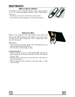
Page 12: ...ars on the display or in any case every 2 months or even more frequently in case of particularly inten sive use of the hood Alarm reset Switch off the hood and the lights If the 24h function has been...

Page 13: ...e Lighting support and pull it out of from the Hood Extract the lamp from the Support Replace with another of the same type making sure that the two pins are properly inserted in the lamp holder socke...

Page 14: ...t lock ing levers Lb by unhooking them from their pins Pull Suction Unit forward so that it slides free from the support pins and remove downwards from the air outlet Use a wet cloth and some detergen...

Page 15: ...JP 1 5 15 120mm 2...

Page 16: ...JP 1 6 16...

Page 17: ...2 2 1 7 1 1 7 1a 1 7 1b 1 10 1 D 150 25 2 Ref 11 4 10 12c 6 2 9 x 6 5 12e 2 2 9 x 9 5 12f 4 M6 x 10 12g 4 M6 x 80 12h 4 5 2 x 70 21 1 22 4 6 4 23 4 M6 1 7 1a 7 1 22 23 12h 7 1b 2 2 1 2 2 12c 11 21 12g...

Page 18: ...JP 1 8 18 21 20mm 10mm 11 7mm 10mm 2 4 5mm 20mm 12h 12g 22 23...

Page 19: ...JP 1 9 19 2 2 2 8 8 2 2 1 1 150mm 150mm 10 10 150 25...

Page 20: ...JP 2 0 20 6 7 Vx A B 8 C 9 A B 10 Vx A B C Vx...

Page 21: ...JP 2 1 21 2 12c 2 9x6 5 2 12c 2 9x6 5 4 12f M6x10 12f 12c 12c Cmd Lux 2 24 2 12e 2 9x9 5 2 12c 2 9x6 5 24 12e Cmd 12c Lux...

Page 22: ...JP 2 2 22 A B C D E F G H A B 3 Lo C D 5 5 HI 1 1 E 140 m3 h 24 1 10 FF 24 function 24 function FF 100 EF 200 F 10 G H 24h function 5...

Page 23: ...JP 2 3 23 LR03 AAA 1 5V FF 2 24h function E...

Page 24: ...JP 2 4 24 20 W 2 2 2...

Page 25: ...JP 2 5 25 Ca Lb Ca Lb...

Page 26: ......

Page 27: ......

Page 28: ...nd electronic equipment By ensuring this product is disposed of correctly you will help prevent potential negative consequences for the environment and human health which could oth erwise be caused by...

Reviews: