background image

14

4

5

I = 6x

I = 6x

2X

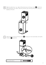
Installation screws provided must be secured with wall plugs (purchase 
separately).

Insert the two screws 

G

 supplied with the hood into the Wall Bracket 

F


as shown and do not tighten all the way to wall leaving 3/16" of the screw 

heads exposed.

F

G

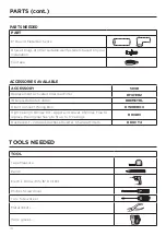
Phillips Screwdriver

Summary of Contents for STILO

Page 1: ...4SSV2 STIL30SSV2 STIL36SSV2 STIL48SSV2 Installation Instructions Use and Care Information Instructions d installation Utilisez et d entretien Instrucciones de instalaci n Informaci n de uso y cuidado...

Page 2: ...NTS 7 PARTS 8 TOOLS NEEDED 10 VENTING METHOD 11 INSTALLING 12 CHOOSING VENTING METHOD 17 ATTACH VENTING DUCTING 18 ATTACH VENTING NON DUCTED RECIRCULATING 22 CONNECTING HOUSE POWER 26 OPERATING THE CO...

Page 3: ...ment is being called 4 You can fight the fire with your back to an exit Based on Kitchen Firesafety Tips published by NFPA WARNING TOREDUCETHERISKOFFIREORELECTRICSHOCK donotusethisfanwith any solid st...

Page 4: ...nd either through the wall or the roof The length of the ductwork and the number of elbows should be kept to a minimum to provide efficient performance The size of the ductwork should be uniform Do no...

Page 5: ...y plastic nonmetallic gaskets or other materials DO NOT use for grounding DO NOT ground to a gas pipe DO NOT have a fuse in the neutral or grounding circuit A fuse in the neutral or grounding circuit...

Page 6: ...6 RANGE HOOD DIMENSIONS DRAFT 27 AP 24 30 36 48...

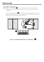
Page 7: ...7 INSTALLATION HEIGHT REQUIREMENTS MIN 24 OVER ELECTRIC MIN 30 OVER GAS Min 24 Min 30...

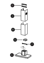
Page 8: ...pic Lower Chimney 1 C Telescopic Upper Chimney 1 D Chimney Brackets 2 E Damper Flaps 2 F Hood wall Brackets 1 REF PART G Pozi Screws 3 16 x 1 3 4 6 H Pozi Screws 1 8 x 3 16 2 I Torx Screws 1 8 x 7 16...

Page 9: ...9 B A F C D E...

Page 10: ...Drill Bit Phillips Screwdriver Torx Screwdriver Metal sheers Work gloves ACCESSORIES AVAILABLE ACCESSORY SKU Replacement Activated Charcoal Filter FILTER2 Wireless Remote Control REMCTRL Direct Conne...

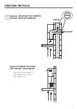
Page 11: ...11 VENTING METHOD Option 1 REAR OR TOP VENTED Ducted Venting Installation Option 2 RECIRCULATING Non ducted recirculation 1 Requires purchase of Activated Charcoal Accessory kit Horizontal Vertical 6...

Page 12: ...iling or upper limit at the center of the area in which the hood will be installed Draw a horizontal line Y where the bottom edge of the hood will be located a minimum of 24 above an electric cooking...

Page 13: ...D on the wall as shown below the first bracket at the height of the upper chimney section C supplied and aligning the center notch with the vertical line 3 Mark the wall at the centers of the holes in...

Page 14: ...ovided must be secured with wall plugs purchase separately Insert the two screws G supplied with the hood into the Wall Bracket F as shown and do not tighten all the way to wall leaving 3 16 of the sc...

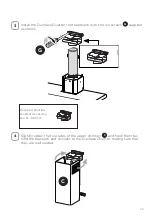
Page 15: ...15 I 6x 6 7 Use a level to insure that Wall Bracket F is level and then fully secure the two screws Hook the hood body onto the hood wall bracket F F A F...

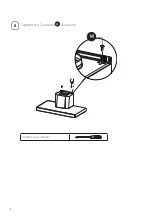
Page 16: ...16 8 Tighten the 2 screws H as shown H Phillips Screwdriver...

Page 17: ...17 CHOOSING VENTING METHOD VENTED RECIRCULATING Go to Pg 18 Go to Pg 22...

Page 18: ...the 6 metal ductwork to the Roof or Wall Cap and then attach ductwork Seal with foil tape Install the Damper flaps E that are included with hood by snapping the tabs into place inside the top of the...

Page 19: ...19 3 Install the 2 Chimney brackets D to the middle and upper holes and secure with screws G as shown L 4x G D D Phillips Screwdriver...

Page 20: ...re the sides to the brackets by using the 4 screws I Slightly widen the two sides of the upper chimney C and hook them behind the brackets D making sure that they are well seated N 4x D C C I Torx Scr...

Page 21: ...laterally to the hood body using the 2 screws L supplied N 2x Slightly widen the two sides of the the lower chimney hood B and hook them between the upper section and the wall making sure that they a...

Page 22: ...lied as shown Only for the recirculation version connect the hood to the Air outlet Con nect 6 metal ductwork to the hood air outlet with foil tape The 6 duct ing needs to be cut to the size of the di...

Page 23: ...imney C and hook them be hind the brackets and connect to the Ductless Diverter making sure that they are well seated Install the Ductless Diverter not supplied with the wo screws G supplied as shown...

Page 24: ...hased separately W 5 6 Secure the sides to the brackets D by using the 4 screws I Attach a charcoal filter in the correct position and block it by the attaching hooks as shown Unlock the hooks push to...

Page 25: ...er chimney hood B laterally to the hood body using the 2 screws H supplied N 2x Slightly widen the two sides of the the lower chimney hood B and hook them between the upper section and the wall making...

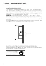
Page 26: ...Consult a qualified electrician if the grounding instructions are not com pletely understood or if doubt exists as to whether the appliance is properly grounded Do not use an extension cord If the po...

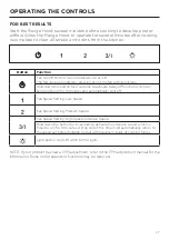
Page 27: ...blower On or Off The fan can be operated by pressing any of the fan setting buttons Hold down this button for 2 seconds to activate Delay off function which will keep the fan on for 15 minutes and au...

Page 28: ...n or more frequently for par ticularly heavy usage and can be washed in a dishwasher Remove the Filters one at a time pushing them towards the back of the unit and at the same time pulling downward Wa...

Page 29: ...ng them towards the back of the unit and at the same time pulling downward Remove the saturated charcoal filter by releasing the hooks Fit the new filter and fasten it in its correct position Replace...

Page 30: ...30 WIRING DIAGRAM...

Page 31: ...ng from accident alteration misuse abuse fire flood acts of God improper installation installation not in accordance with electrical or plumbing codes or Faber documentation or use of products not app...

Page 32: ...N CESSAIRES 40 M THODE D A RATION 41 INSTALLATION 42 CHOISIR LA M THODE D A RATION 47 RACCORDEZ L A RATION DUCTED 48 RACCORDEZ L A RATION NON DUCTED RECIRCULATING 52 BRANCHER LE COURANT DOMESTIQUE 56...

Page 33: ...srisquerdevousbr ler c N UTILISEZ PAS D EAU ni de torchons ou de serviettes mouill s pour viter une violente explosion de vapeur d Utilisez un extincteur UNIQUEMENT si 1 Vous savez que vous avez un ex...

Page 34: ...ure du mur ext rieur ou du plancher tout autour du capuchon Les conduits flexibles ne sont pas recommand s Les conduits flexibles cr ent une contre pression et des turbulences d air qui r duisent cons...

Page 35: ...a terre un tuyau de gaz NE PAS pr voir de fusible dans le circuit neutre ou de mise la terre Un fusible dans le circuit neutre ou de mise la terre pourrait provoquer un choc lectrique Demandez conseil...

Page 36: ...36 DIMENSIONS DE LA HOTTE DRAFT 27 AP 24 30 36 48...

Page 37: ...37 EXIGENCE D INSTALLATION EN HAUTEUR MIN 24 SUR LECTROM NAGER LECTRIQUE MIN 30 SUR LECTROM NAGER GAZ Min 24 Min 30...

Page 38: ...ure t l scopique 1 C Chemin e sup rieure t lescopique 1 D Supports de chemin e 2 E Volets de registre 2 F Supports muraux de la hotte 1 R F PI CE QT G Vis Pozi 3 16 x 1 3 4 6 H Vis Pozi 1 8 x 3 16 2 I...

Page 39: ...39 B A F C D E...

Page 40: ...po Tournevis Phillips Tournevis Torx Ciseaux m taux Gants de travail ACCESSOIRES DISPONIBLES ACCESSOIRES SKU Replacement filtre charbons actifs FILTER2 Commande distance sans fils REMCTRL Bo tier de c...

Page 41: ...RATION Option 1 ARRI RE OU DESSUS A R Installation de la ventilation par conduits Option 2 RECIRCULATION Sans conduit recirculation 1 N cessite l achat du kit d accessoires pour charbon actif Horizont...

Page 42: ...e destin e l installation de la hotte Tracez une ligne horizontale Y l endroit o le bord inf rieur de la hotte sera situ un minimum de 24 po au dessus d une surface de cuisson lectrique et de 30 po au...

Page 43: ...e indiqu sous le premier la hauteur de la section sup rieure de la chemin e C fournie et en alignant le centre encoche avec la ligne verticale 3 Marquez le mur aux centres des trous dans le support et...

Page 44: ...fournies doivent tre fix es avec des chevilles murales acheter s par ment Ins rez les deux vis G fournies avec la hotte dans le support mural F comme indiqu sans les serrer fond en laissant 3 16 des t...

Page 45: ...45 I 6x 6 7 Utilisez un niveau pour vous assurer que le support mural F est de niveau puis fixer compl tement les deux vis Accrochez le corps de la hotte son support mural F F A F...

Page 46: ...46 8 Serrez les 2 vis H comme illustr H Tournevis Phillips...

Page 47: ...47 CHOISIR LA M THODE D A RATION A RATION RECIRCULATION Allez la page 48 Allez la page 52...

Page 48: ...tallique de 6 po au capuchon de toit ou de mur puis fixez la gaine Scellez avec du ruban adh sif Installez les volets du clapet E fournis avec la hotte en mettant les languettes en place l int rieur d...

Page 49: ...49 3 Installez les 2 supports de chemin e D dans les trous du milieu et du haut et fixez les avec des vis G comme indiqu L 4x G D D Tournevis Phillips...

Page 50: ...c t s aux supports l aide des 4 vis I largissez l g rement les deux c t s de la chemin e sup rieure C et accrochez les derri re les supports D en vous assurant qu ils sont bien en place N 4x D C C I...

Page 51: ...t ralement B sur le corps de la hotte l aide des 2 vis L fournies N 2x largissez l g rement les deux c t s de la hotte inf rieure B et accro chez les entre la section sup rieure et le mur en veillant...

Page 52: ...ration Uniquement pour la version recirculation raccordez la hotte la prise d air Raccordez un conduit m tallique de 6 po la sortie d air de la hotte avec du ruban adh sif m tallique Le conduit de 6 p...

Page 53: ...ccro chez les derri re les supports et raccordez les au d flecgteur sans conduit en vous assurant qu ils sont bien en place Installez le d flecteur sans conduit non fourni avec les vis sans fin G four...

Page 54: ...nt W 5 6 Fixez les c t s aux supports D l aide des 4 vis I Fixez un filtre charbon dans la position appropri e et bloquez le par les crochets de fixation comme illustr D verrouillez les crochets pouss...

Page 55: ...e inf rieure lat ralement B sur le corps de la hotte l aide des 2 vis H fournies N 2x largissez l g rement les deux c t s de la hotte inf rieure B et accro chez les entre la section sup rieure et le m...

Page 56: ...ue Consultez un lectricien qualifi si vous ne comprenez pas parfaitement les instructions de mise la terre ou si vous avez des doutes quant la mise la terre de l appareil N utilisez pas de rallonge le...

Page 57: ...eut tre actionn en appuyant sur l un des boutons de r glage du ventilateur Maintenez ce bouton enfonc pendant 2 secondes pour activer la fonction d arr t diff r qui maintient le ventilateur en marche...

Page 58: ...fonctionnement ouplusfr quemment en cas d utilisation particuli rement intensive possibilit de les laver au lave vaisselle Retirez les filtres un par un en les poussant vers l arri re de l appareil et...

Page 59: ...m me temps vers le bas Retirez le filtre charbon satur en d gageant les crochets Installez le nouveau filtre et fixez le dans sa position correcte Remettez le en place en veillant ce que la poign e so...

Page 60: ...60 SCH MA DE C BLAGE...

Page 61: ...ommages d coulant d un accident d une modification de l utilisation incorrecte ou abusive d un incendie d une inondation d un cas de force majeure d une installation inad quate d une installation non...

Page 62: ...IAS 70 M TODO DE VENTILACI N 71 INSTALACI N 72 SELECCI N DEL M TODO DE VENTILACI N 77 ACOPLAMIENTO VENTILACI N CANALIZADO 78 ACOPLAMIENTO VENTILACI N RECIRCULACI N SIN CANALIZADO 82 CONEXI N DE LA ENE...

Page 63: ...NO UTILICE AGUA incluyendo pa os de cocina o toallas mojadas se producir una violenta explosi n de vapor d Utilice un extintor SOLO si 1 Sabe que tiene un extintor de clase ABC y ya sabe c mo manejar...

Page 64: ...uctos Utilice masilla para sellar la pared exterior o la abertura del suelo alrededor de la tapa No se recomienda utilizar conductos flexibles Los conductos flexibles crean con trapresi n y turbulenci...

Page 65: ...ara la conexi n a tierra NO conecte a tierra una tuber a de gas NO tenga un fusible en el circuito neutro o de conexi n a tierra Un fusible en el circuito neutro o de conexi n a tierra podr a provocar...

Page 66: ...66 DIMENSIONES DE LA CAMPANA EXTRACTORA DRAFT 27 AP 24 30 36 48...

Page 67: ...67 REQUERIMIENTOS DE ALTURA DE INSTALACI N M N 24 SOBRE ELECTRICIDAD M N 30 SOBRE GAS M n 24 Min 30...

Page 68: ...C Chimenea Superior Telesc pica 1 D Soportes de chimenea 2 E Aletas del Amortiguador 2 F Soportes de la pared de la Campana 1 REF PIEZA CANT G Tornillos Pozi 3 16 x 1 3 4 6 AL Tornillos Pozi 1 8 x 3...

Page 69: ...69 B A F C D E...

Page 70: ...ca 5 16 Destornillador Phillips Destornillador Torx Cizallas de metal Guantes de trabajo ACCESORIOS DISPONIBLES ACCESORIO SKU Sustituci n del Filtro de Carb n Activado FILTER2 Control Remoto Inal mbri...

Page 71: ...N Opci n 1 CON VENTILACI N TRASERA O SUPERIOR Instalaci n de Ventilaci n por Conductos Opci n 2 RECIRCULACI N Sin conductos recirculaci n 1 Requiere la compra del kit de Accesorios de Carb n Activado...

Page 72: ...o l mite superior en el centro del rea en la que se instalar la campana Dibuje una linea horizontal Y donde se ubicar el borde inferior de la campana a un m nimo de 24 sobre una superficie de cocci n...

Page 73: ...omo se muestra debajo del primer soporte a la altura de la secci n superior de la chimenea C suministrada y alineando el centro muesca con la l nea vertical 3 Marque la pared en los centros de los agu...

Page 74: ...asegurarse con tacos de pared se compran por separado Inserte los dos tornillos G suministrados con la campana en el Soporte de Pared F como se muestra y no apriete del todo a la pared dejando 3 16 d...

Page 75: ...6x 6 7 Utilice un nivel para asegurarse de que el Soporte de Pared F est nivelado y luego fije completamente los dos tornillos Enganche el cuerpo de la campana en el soporte de pared de la campana F F...

Page 76: ...76 8 Apriete los 2 tornillos AL como se muestra AL Destornillador Phillips...

Page 77: ...77 SELECCI N DEL M TODO DE VENTILACI N VENTILADO RECIRCULACI N Vaya a la P g 78 Vaya a la P g 82...

Page 78: ...6 a la Tapa del Techo o de la Pared y luego fije el conducto Selle con cinta adhesiva Instale las aletas del Amortiguador E que se incluyen con la campana encajando las leng etas en su lugar dentro d...

Page 79: ...79 3 Instale los 2 soportes de la Chimenea D en los agujeros centrales y superiores y f jelos con tornillos G como se muestra L 4x G D D Destornillador Phillips...

Page 80: ...os a los soportes utilizando los 4 tornillos I Ensanche ligeramente los dos lados de la chimenea C superior y eng nchelos detr s de los soportes D asegur ndose de que est n bien asentados N 4x D C C I...

Page 81: ...cuerpo de la campana utilizando los 2 tornillos L suministrados N 2x Ensanche ligeramente los dos lados de la campana inferior de la chimenea B y eng nchelos entre la secci n superior y la pared aseg...

Page 82: ...estra Solo para la versi n de recirculaci n conecte la campana a la salida de Aire Conecte los conductos met licos de 6 a la salida de aire de la cam pana con cinta adhesiva El conducto de 6 debe cort...

Page 83: ...n chelos detr s de los soportes y con ctelos al Desviador Sin Ducto asegu r ndose de que est n bien asentados Instale el Desviador Sin Ducto no suministrado con los dos tornillos G suministrados tal c...

Page 84: ...Asegure los lados a los soportes D utilizando los 4 tornillos I Coloque un filtro de carb n vegetal en la posici n correcta y bloqu elo por los ganchos de fijaci n como se muestra Desbloquee los ganch...

Page 85: ...ior B lateralmente al cuerpo de la campana utilizando los 2 tornillos AL suministrados N 2x Ensanche ligeramente los dos lados de la campana inferior de la chimenea B y eng nchelos entre la secci n su...

Page 86: ...suponer un riesgo de descarga el ctrica Consulte a un electricista cualificado si no comprende completamente las instrucciones de conexi n a tierra o si tiene dudas sobre si el aparato est correctamen...

Page 87: ...puede accionar pulsando cualquiera de los botones de ajuste del ventilador Mantenga pulsado este bot n durante 2 segundos para activar la funci n de Retraso de apagado que mantendr el ventilador ence...

Page 88: ...rse cada 2 meses de funcionamiento o con mayor frecuencia en caso de uso especialmente intenso y pueden lavarse en el lavavajillas Retire los filtros de uno en uno empuj ndolos hacia la parte posterio...

Page 89: ...ior de la unidad y al mismo tiempo tirando hacia abajo Retire el filtro de carb n saturado soltando los ganchos Coloque el nuevo filtro y f jelo en su posici n correcta Vuelvaacolocarlo teniendocuidad...

Page 90: ...90 DIAGRAMA DE CABLEADO...

Page 91: ...zados contra cualquier defecto de materiales o mano de obra para el comprador original por un per odo de 1 a o a partir de la fecha de compra original requiere prueba de compra Esta garant a cubre man...

Page 92: ...991 0656 732_01 210930 D000000008184_00...

Reviews: