EN
1
11
ELECTRICAL CONNECTION
• Connect the hood to the mains through a two-pole switch hav-
ing a contact gap of at least 3 mm.
• Remove the grease filters (see paragraph Maintenance) being
sure that the connector of the feeding cable is correctly inserted
in the socket placed on the side of the fan.
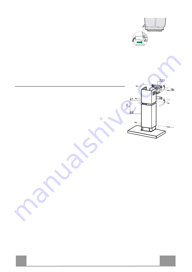
Flue assembly
Upper exhaust flue
• Slightly widen the two sides of the upper flue and hook them
behind the brackets
7.2.1
, making sure that they are well
seated.
• Secure the sides to the brackets by using the 4 screws
12c
(2,9
x 9,5) supplied.
• Make sure that the outlet of the extensions pieces is aligned
with the chimney outlets.
Lower exhaust flue
• Slightly widen the two sides of the flue and hook them be-
tween the upper flue and the wall, making sure that they are
well seated.
• Fix the lower part laterally to the hood body by using the 2
screws
12c
(2,9 x 9,5) supplied.
12b
Summary of Contents for Stilux 90
Page 8: ...EN 8 8 Dimensions...
Page 18: ...FR 1 18 Encombrement...
Page 28: ...DE 2 28 Platzbedarf...
Page 38: ...ES 3 38 Dimensiones...
Page 44: ...GR 4 44 650 mm 120 mm...
Page 45: ...GR 4 45 0 04 mbar 8...
Page 46: ...GR 4 46...
Page 48: ...GR 4 48...
Page 50: ...GR 5 50 2 Vr 12a 12a Vr 12a Vr o150 120 mm o120 mm 9 9 120 150 2 7 2 1 15 2 15 150 mm...
Page 51: ...GR 5 51 3 mm 7 2 1 4 12c 2 9 x 9 5 2 12c 2 9 x 9 5 12b...
Page 52: ...GR 5 52 T1 T2 T3 T4 L T1 T2 T1 T2 T3 T1 T3 2 30 T1 T2 T3 T4 T4 T1 T4 2 6 L...
Page 53: ...GR 5 53 2 4...
Page 54: ...RU 5 54 650 I 120...
Page 55: ...RU 5 55 0 04 8...
Page 56: ...RU 5 56...
Page 58: ...RU 5 58...
Page 60: ...RU 6 60 2 Vr 12a 12a Vr 12a Vr 150 120 120 9 9 120 150 2 7 2 1 15 2 15 150...
Page 61: ...RU 6 61 3 7 2 1 4 12c 2 9 x 9 5 2 12c 2 9 x 9 5 12b...
Page 62: ...RU 6 62 T1 T2 T3 T4 L T1 T2 T1 T2 T3 T1 T3 2 30 T1 T2 T3 T4 T4 T1 T4 2 6 L...
Page 63: ...RU 6 63 2 4...
Page 68: ...TR 6 68 Boyutlar...
Page 74: ......
Page 75: ......


