7
<
<
<
<
UK
IRL
4
Instructions for installation
4.1
Gas connection
1
Installation pipes should be in accordance with IGE/UP/1B. Pipe work from the meter
to the appliance must be of adequate size.
2
The complete installation including the meter must be tested for soundness and
purged as described in the above code.
3
A means of isolation must be provide in the supply to facilitate servicing.
4
The connection should be made in 8 mm copper or similar semi flexible tube (max. 1
meter). Ensure that the gas pipe does not interfere with the removal or replacement
of the burner tray of the controls.
5
The supply gas feed line should enter the appliance through one of the openings in the
appliance case. Openings are at the back and right side.
6
The gas connection is nut and olive suitable for 8 mm pipe.
7
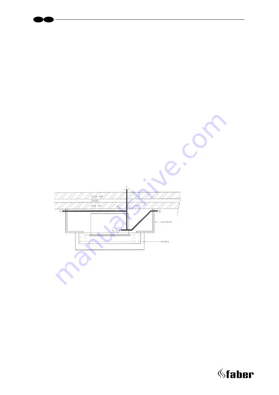
Where a gas pipe passes through a void, wall or cavity it must be fully enclosed in a
sleeve, and the opening from the void behind the fire surround to the cavity wall must
be sealed.
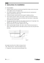
Gas supply routes when fire is fitted in a deep surround
A & B = Behind surround – Sleeve pipe through surround
C = Through wall – Pipe must be sleeved and sealed to fire
Fig.4.1

