background image

25

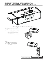
Mark the holes for attaching the hood to the cabinet.  Verify the measurement with 
the diagram on the previous page.

3

Attach the Hood body with 4 screws 

E

 from the bottom available with the hood.

4

E

3R]L6FUHZV[ 


Pozi Screwdriver

MOUNTING RANGE HOOD UNDER THE CABINET

Summary of Contents for TIVANO TVNO30SS395

Page 1: ...TVNO30SS395 TVNO36SS395 Installation Instructions Use and Care Information Instructions d installation Utilisez et d entretien Instrucciones de instalaci n Informaci n de uso y cuidado TIVANO...

Page 2: ...ection Knockout s Choose Vertical or Horizontal Electrical Connection Knockout s 12 Ducted venting method options 14 Ducted 7 round outlet 15 Ducted 3 1 4 x 10 Rectangular Outlet on top 17 Ducted 3 1...

Page 3: ...QJ FDOOHG RX FDQ JKW WKH UH ZLWK RXU EDFN WR DQ H LW Based on Kitchen Firesafety Tips published by NFPA WARNING TOREDUCETHERISKOFFIREORELECTRICSHOCK donotusethisfanwith any solid state speed control d...

Page 4: ...extend either through the wall or the roof The length of the ductwork and the number of elbows should be kept to a minimum to SURYLGH HI FLHQW SHUIRUPDQFH 7KH VL H RI WKH GXFWZRUN VKRXOG EH XQLIRUP R...

Page 5: ...Thisapplianceshouldbeconnecteddirectlytothefuseddisconnect orcircuitbreaker WKURXJK H LEOH DUPRUHG RU QRQPHWDOOLF VKHDWKHG FRSSHU FDEOH OORZ VRPH VODFN LQ the cable so the appliance can be moved if se...

Page 6: ...6 RANGE HOOD DIMENSIONS RECTANGULAR OUTLET AIR...

Page 7: ...7 MIN 24 OVER ELECTRIC MIN 30 OVER GAS CIRCULAR OUTLET AIR Min 24 Min 30 INSTALLATION HEIGHT REQUIREMENTS...

Page 8: ...8 PARTS REF PART A Hood body Includes Controls Light Filters Blower 1 B Damper 1 C 7 Round Flange 1 D Grid Only for Canadian Market 1 REF PART E 3R L 6FUHZV 4 F 7RU 6FUHZV 4 PARTS INCLUDED C B A D...

Page 9: ...per Wire connectors Power Supply Cable Drywall plugs or other suitable wall fasteners based on your installation DOO DS 5RRI DS 1HHGV WR EH SXUFKDVHG VHSDUDWHO TOOLS NEEDED TOOL Tape Measure Pencil OH...

Page 10: ...ured Install Grid D with the two screws removed from step 2 Screw the protection grid into the location shown in the picture below The correct location has a rectangular cut out to accommodate the gri...

Page 11: ...he back of the hood and pulling down at the same time Remove the wiring box cover by unscrewing the 2 screws Preparing the hood for electrical knockouts 7 1 2 13 16 13 16 CHOOSE VERTICAL OR HORIZONTAL...

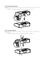
Page 12: ...with a screwdriver or other tool During the installation thread Power Supply Cable through this hole 3 7RS ROH 9HUWLFDO Choose the top hole for the electric connection and break with a screwdriver or...

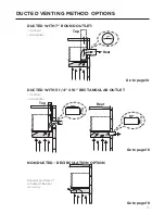
Page 13: ...OUTLET Vertical Horizontal DUCTED WITH 3 1 4 X 10 RECTANGULAR OUTLET Vertical Horizontal 7 Rear Top 10 3 1 4 10 3 1 4 Rear Top Go to page 14 Go to page 16 NON DUCTED RECIRCULATION OPTION Requires pur...

Page 14: ...ere indicated Remove both the rectangular and semicircle areas with metal shears Rear Top 7 Required 7 Round Damper purchase separately 1 Caution If an elbow is required do it as far away from the hoo...

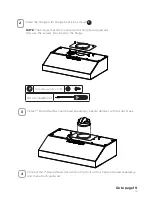
Page 15: ...tely Secure damper with foil duct tape Connect the 7 Round Metal Ductwork to the Roof or Wall Cap purchased separately and then attach ductwork Go to page 19 2 3 Torx Screwdriver NOTE The Flange must...

Page 16: ...luded rectangular air outlet with two screws F Connect the metal ductwork to the Roof or Wall Cap purchased separately and then attach ductwork Rear Top Top 3 1 4 x 10 DUCTED 3 1 4 X 10 RECTANGULAR OU...

Page 17: ...ectangular air outlet with two screws F 1 2 Torx Screwdriver F 7RU 6FUHZV DUCTED 3 1 4 X 10 RECTANGULAR OUTLET REAR Caution If an elbow is required do it as far away from the hood s exhaust opening as...

Page 18: ...he same screw Cut the cover where indicated in picture b1 Discard Recycle upper pieces of blower cover InstalltheActivatedCharcoalFilterpurchasedseparately whereindicatedinthepicture C c NON DUCTED RE...

Page 19: ...19 CHOOSING THE MOUNTING METHOD Installation for Mounting on the Wall Installation for Mounting to the cabinet Page 20 Page 24...

Page 20: ...t the center of the area in which the hood will be installed Draw a horizontal line I from where the bottom edge of hood will be located to a minimum of 24 above an electric cooking surface and 30 abo...

Page 21: ...J distance on the left and right of the vertical line H 3 2 3 4 2 3 4 8 7 16 8 7 16 Mark the wall for lower anchors Mark 1 below the Step 2 Upper Anchors Take care to keep level 30 27 30 27 3 8 3 8 36...

Page 22: ...HU SRLQWV PDUNHG LQ VWHS Iffastenerlocationsdonotalignwiththestuds insertthepurchasedwallplugsintheholes In upper holes use two of the supplied screws E to secure the hood body to the wall 5 Pozi Scre...

Page 23: ...23 Using two remaining screws E anchor the hood in lower holes as indicated 6 MOUNTING RANGE HOOD ON WALL Pozi Screwdriver E 3R L 6FUHZV...

Page 24: ...on the Range Hood for the power cord See Section CHOOSE VERTICAL OR HORIZONTAL ELECTRICAL CONNECTION KNOCKOUT S and pass the cord through the appropriate hole Lift the hood to the cabinet and pass th...

Page 25: ...he hood to the cabinet Verify the measurement with the diagram on the previous page 3 Attach the Hood body with 4 screws E from the bottom available with the hood 4 E 3R L 6FUHZV Pozi Screwdriver MOUN...

Page 26: ...Connections Attach the White lead of the Power Supply A to the White lead of the Range Hood D with a twist on type connector Attach the Black lead of the Power Supply to the Black lead of the Range H...

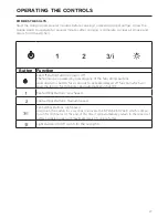
Page 27: ...e fan setting buttons Hold down this button for 2 seconds to activate delayed off function which will keep the fan On for 15 minutes and automatically shut Off Fan Settings Buttons Low Speed Fan Setti...

Page 28: ...ERS 7KH PHWDO JUHDVH OWHUV FDQ EH FOHDQHG LQ KRW GHWHUJHQW VROXWLRQ RU ZDVKHG in the dishwasher They should be cleaned every 2 months use or more frequently if use is particularly heavy NOTES OHDQLQJ...

Page 29: ...plica tions Fit the new filter by hooking it into its seating or by fixing it with the two screws for Cana dian applications 1 2 3 REPLACING ACTIVATED CHARCOAL FILTER The Activated Charcoal Filters ar...

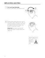
Page 30: ...3 1 5 W Led Type GU10 bulb Remove the bulb See the picture Replace the bulb with a new one of the same type making sure that you insert the two pins properly into the housings on the lamp holder and t...

Page 31: ...31 WIRING DIAGRAM U SFBU PEF 6 3 3 7 7 4 0503 41 7 _ 8 5 8 5 41 5 7 7 8 5 8 5 03 7 5 03 6 3 7 38 03 6 3 6 7 5 4 530 53 4 03 3 38 3 SFE WMU 3 3 3 3 3 3 5 7 5 3 7 5 3...

Page 32: ...outside the United States Canada or Latin America including any non UL or C UL or non NOM approved Franke Faber range hoods are excluded from Warranty coverage Expenses for travel and transportation...

Page 33: ...low All warranty claims must include the following for processing 1 Proof of purchase from Franke or Faber Authorized Retailer 2 Original purchaser s name address included city state zip email address...

Page 34: ...991 0xxx xxx_01 220201 D0000xxxx_00...

Reviews: