background image

11

7

Install Damper that is included with the Hood before 

connecting to the ductwork.

Only for Ducted Venting Installation

8

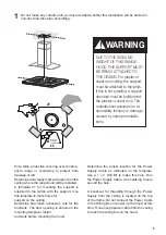
Now take either your wood screws or bolts 

depending on your set-up and screw all four 

into the pilot holes and leave 1/4" of the 

heads exposed.

Next install a UL or CSA listed strain relief 

in the wiring box so that the screws can 

be tightened after the chimney support is 

attached to the ceiling.

Now lift the chimney support into it's final 

position and feed the electrical supply through 

the strain relief.

Next position the chimney support so that 

the large end of the keyhole slots are over 

the ceiling attachment screws or bolts. Then 

push the chimney support so that the bolts 

are in the neck of the slots.  Tighten all four 

screws or bolts securely.

•  The frame mountings must be secure to 

withstand the weight of the hood and any 

stresses caused by the occasional side 

thrust applied to the device. On completion, 

check that the base is stable, even if the 

frame is subjected to bending.

•  In all cases where the ceiling is not 

strong enough at the suspension point, 

the installer must provide strengthening 

using suitable plates and backing pieces 

anchored to the structurally sound parts.

Summary of Contents for TRATTO TRATIS36SSV

Page 1: ...TRATIS36SSV TRATTO IS 36 Installation Instructions Use and Care Information Instructions d installation Utilisez et d entretien Instrucciones de instalación Información de uso y cuidado ...

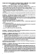
Page 2: ...e with your back to an exit Based on Kitchen Firesafety Tips published by NFPA WARNING TO REDUCE THE RISK OF FIRE OR ELECTRIC SHOCK do not use this fan with any solid state speed control device WARNING TO REDUCE THE RISK OF FIRE ELECTRICAL SHOCK OR INJURY TO PERSONS OBSERVE THE FOLLOWING 1 Use this unit only in the manner intended by the manufacturer If you have any questions contact the manufactu...

Page 3: ...O NOT terminate the ductwork in an attic or other enclosed space DO NOT use 4 laundry type wall caps Flexible type ductwork is not recommended DO NOT obstruct the flow of combustion and ventilation air Failure to follow venting requirements may result in a fire WARNING VENTING REQUIREMENTS Determine which venting method is best for your application Ductwork can extend either through the wall or th...

Page 4: ...copper cable Allow some slack in the cable so the appliance can be moved if servicing is ever necessary A UL Listed 1 2 conduit connector must be provided at each end of the power supply cable at the appliance and at the junction box When making the electrical connection cut a 1 1 4 hole in the wall A hole cut through wood must be sanded until smooth A hole through metal must have a grommet Electr...

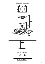
Page 5: ...5 RANGEHOOD DIMENSIONS Min 24 Min 30 ...

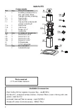
Page 6: ...omponents 12f 2 Screws 3 16 x 9 16 12c 2 Screws 1 8 x 1 4 12e 4 Screws 1 8 x 3 8 12q 4 Screws 1 4 x 9 16 21 1 Drilling template 22 4 1 4 int dia washers Qty Documentation 1 Instruction Manual 1 2 2 2 1 21 7 1 12q 22 12c 12e 12f 24 7 1a 7 1b Available Accessories High Ceiling Kit that replaces the upper flue sku HIGH2 Ductless Kit Includes Ductless Diverter Charcoal Filters Lower chimney with vent ...

Page 7: ...7 Choose your ducting method Non Ducted Recirculation Ducted Venting Installation Requires Ductless Accessory Kit purchased separately 6 ...

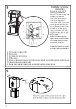
Page 8: ...Supply Cable Use caulking to seal around the hole A knockout for threading through the Power Supply from the ceiling is located on the top of the frame Do not connect the Power Cable to the Wiring Box or power up the hood at this time Run enough power cable from the ceiling to reach the wiring box on the hood Ø 10 mm x4 21 1 1 4 Do not make any cutouts until you have decided whether this installat...

Page 9: ... need to adjust the height of the frame proceed as follows Unfasten the metric screws joining the two columns located at the sides of the frame 1 2 3 4 5 6 Adjust the frame to the height required then refit all the screws removed as above Loosen the two screws fastening the upper chimney and remove this from the upper frame 1 4 MIN 740 mm MAX 940 mm 2 3 5 6 ...

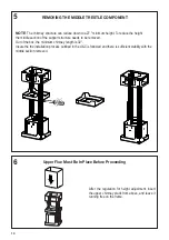
Page 10: ...OTE The chimney structure can reduce down to a 27 minimum height To reduce the height the middle section of the support structure needs to be removed Out of the box the minimum chimney length is 32 Insure the the installation process outlined in the U C is followed and there is sufficient stability with the middle section removed REMOVING THE MIDDLE TRESTLE COMPONENT 6 After the regulation for hei...

Page 11: ...rough the strain relief Next position the chimney support so that the large end of the keyhole slots are over the ceiling attachment screws or bolts Then push the chimney support so that the bolts are in the neck of the slots Tighten all four screws or bolts securely The frame mountings must be secure to withstand the weight of the hood and any stresses caused by the occasional side thrustappliedt...

Page 12: ... supply to the Black lead of the rangehood with a twist on type wire connector 1 The UPPER CHIMN COVER C in FIGURE attaches to the top of support structure using screwsprovided GinFIGU 13 If using the High Cei ChimneyKit usetheUPP CHIMNEY COVER supp with the kit Slide up attach the UPPER CHIMN COVER 2 Attach the duct work to DAMPER M in FIGURE Makesuretosealalljoints duct tape to prevent leaks 3 T...

Page 13: ...and attach the UPPER CHIMNEY COVER 2 Attach the duct work to the DAMPER M in FIGURE 1 Makesuretosealalljointswith duct tape to prevent leaks 3 The LOWER CHIMNEY COVER B in FIGURE 13 attaches using two screws provided G in FIGURE 13 Install the LOWER CHIMNEY COVER by sliding it up over the support and the UPPER CHIMNEY COVER For ductless installations line up the DUCTLESS DIVERTER EXTENSIONS HORIZO...

Page 14: ... from the hood canopy Remove any activated charcoal filters Lift the hood canopy and engage the screws 12f in the slots as far as they will go Working from below fix the hood canopy to the frame where indicated using the 4 screws 12q and 4 washers 22 provided then tighten all the screws securely I I T Attachment of Hood Canopy ...

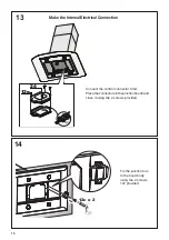
Page 15: ...ontrol connector Cmd Placetheconnectorsinthejunctionbox24and close it using the 4 screws provided 14 12c x 2 Fix the junction box to the hood body using the 2 screws 12c provided H Make the Internal Electrical Connection ...

Page 16: ...oal Filter Accessory sku FILTER2 purchased separately Attach a charcoal filter in the correct position and block it by the fixing hooks as shown Unlock the fixing hooks towards the back of the insert hood to remove Reinstall the grease filters from the hood canopy 15 ...

Page 17: ...y off function which will keep the fan on for 15 minutes and automatically shut off T2 Fan settings buttons Low speed T3 Fan settings buttons Medium speed T4 Fan settings buttons High speed Intensive speed Hold down the button for 2 seconds to activate the intensive speed which is timed to run for 10 minutes At the end of this time it will automatically return to the speed set before Suitable to d...

Page 18: ... handle faces forwards No water can be present in filters before installing back in hood Replacing Activated Charcoal Filter The filter is not washable and cannot be regener ated and must be replaced approximately every 4 monthsofoperation ormorefrequentlyforparticu larly heavy usage Remove the Filters one at a time pushing them towardsthebackoftheunitandatthesametime pulling downward Removethesat...

Page 19: ...19 Wiring Diagram 991 0439 886 H90 305 D002531_01 ...

Page 20: ...rom accident alteration misuse abuse fire flood acts of God improper installation installation not in accordance with electrical or plumbing codes or Faber documentation or use of products not approved by Faber 5 Replacement parts or repair labor costs for units operated outside the United States or Canada including any non UL or C UL approved Faber range hoods 6 Repairs to the hood resulting from...

Page 21: ...ie se trouve derrière vous pendant que vous éteignez les flammes D après le guide Kitchen Firesafety Tips publié par la NFPA aux États Unis AVERTISSEMENT POURRÉDUIRELERISQUED INCENDIEOUDECHOCÉLECTRIQUE n utilisez jamaisceventilateurenassociationavecundispositifderéglagedevitesseàsemi conducteurs AVERTISSEMENT POUR RÉDUIRE LES RISQUES D INCENDIE DE CHOC ÉLECTRIQUE OU DE BLESSURE CORPORELLE RESPECTE...

Page 22: ...la longueur des conduits et le nombre de coudes doivent être le pluslimitésquepossible Lediamètredesconduitsdevraitêtreuniforme N installezpasdeuxcoudes ensemble Utilisez un ruban pour canalisations afin de sceller tous les joints du système de conduits Utilisezuncalfeutragepourscellerlesouverturesdanslemurextérieurouleplancher autourduclapet Il n est pas recommandé d utiliser des conduits flexibl...

Page 23: ... permettre le déplacement de l appareil si des travaux d entretien s avéraient nécessaires Un raccord de conduit homologué par l UL de 1 2 doit être installé aux deux extrémités du câble d alimentation au niveau de l appareil et de la boîte de liaison Lors de la réalisation du branchement électrique réalisez un trou de 1 1 4 dans le mur S il s agit d un trou dans le bois il doit être poncé pour le...

Page 24: ...24 DIMENSIONS DE LA HOTTE Min 24 Min 30 ...

Page 25: ... Châssissupérieur 7 1b 1 Châssisinférieur 10 1 Registreø57 8 24 1 Boîtedeliaison Réf Qté Composants d installation 12f 2 Vis3 16 x9 16 12c 2 Vis1 8 x1 4 12e 4 Vis1 8 x3 8 12q 4 Vis1 4 x9 16 21 1 Gabaritdeperçage 22 4 Rondellesdiaint 1 4 Qté Documentation 1 Moded emploi Trousse de cheminée pour plafonds hauts pour remplacer le conduit supèrieur de cheminée No d article HIGH2 Trousse sans conduit Co...

Page 26: ...26 6 Choisissez la méthode de canalisation Exige la trousse d accessoires sans conduit achetée séparément Sans canalisation recirculation Options d installation avec ventilation canalisée ...

Page 27: ...a hotte sera installée et marquez la clairement sur le plafond à l aide d un crayon Un gabarit 21 pour le montage du socle est fournidansl emballage Utilisezcemodèlepour indiquer les trous qui serviront à fixer le socle au plafond Déterminez les ouvertures nécessaires pour les conduits et pratiquez les L ouverture pour la canalisation est représentée sur le gabarit de montage Installez les conduit...

Page 28: ... 3 4 5 6 Réglez le châssis à la hauteur requise puis remettezenplacetouteslesvisenlevéescomme ci dessus Dévissez les deux vis qui fixent la section inférieure de la cheminée et détachez la du châssis inférieur Dévissez les deux vis qui fixent la section supérieure de la cheminée et détachez la du châssis supérieur Les conduits de cheminées doivent être enlevés avant l installation de la hotte ...

Page 29: ...OTE The chimney structure can reduce down to a 27 minimum height To reduce the height the middle section of the support structure needs to be removed Out of the box the minimum chimney length is 32 Insure the the installation process outlined in the U C is followed and there is sufficient stability with the middle section removed REMOVING THE MIDDLE TRESTLE COMPONENT 6 After the regulation for hei...

Page 30: ...rough the strain relief Next position the chimney support so that the large end of the keyhole slots are over the ceiling attachment screws or bolts Then push the chimney support so that the bolts are in the neck of the slots Tighten all four screws or bolts securely The frame mountings must be secure to withstand the weight of the hood and any stresses caused by the occasional side thrustappliedt...

Page 31: ... connected to green ground screw FIGURE 11 Ductless installations require a Ductless Conversion Kit whose components are pictured in FIGURE 12 Do not use the DAMPER M in FIGURE 1 for ductless installations The LOWER CHIMNEY COVER B in FIGURE 1 should be discarded and replaced by the new one with holes from theDuctlessConversionKit D in FIGURE 12 As indicated in FIGURE 12 place the DUCTLESS DIVERTE...

Page 32: ...re nversion onents are E 12 Do MPER M r ductless e LOWER VER B hould be placed by holes from ersionKit FIGURE UCTLESS over the the EASY UCTLESS ENSIONS into the FIGURE 12 DUCTLESS INSTALLATIONS De la même façon placez la section inférieure de la cheminée et fixez la partie inférieure au châssis à l aide des 2 vis enlevées précédemment Pour installation sans conduit uniquement L installation sans c...

Page 33: ...e Retirez tout filtre à charbon actif Soulevez l auvent de la hotte et insérez les vis 12f dans les fentes en les enfonçant le plus possible En passant par le dessous fixez l auvent de la hotte au châssis aux endroits indiqués en utilisant les 4 vis 12q et les 4 rondelles 22 fournies puis serrez fermement toutes les vis Montage de l auvent de la hotte ...

Page 34: ...ecteur de commande Cmd Placezlesconnecteursdanslaboîtedeliaison 24 et refermez la à l aide des 4 vis fournies Fixez la boîte de liaison au bâti de la hotte à l aide des 2 vis 12c fournies Réalisation des branchements électriques internes ...

Page 35: ... article FILTER2 acheté séparément Posez un filtre à charbon à l emplacement adéquat et bloquez le à l aide des crochets de fixation comme illustré Déverrouillez les crochets de fixation vers l arrière de la hotte encastrable pour les enlever Remettez en place les filtres à graisse de l auvent de la hotte ...

Page 36: ...nsive Tenez le bouton enfoncé pendant environ 2 secondes pour activer la vitesse intensive pour une durée de 10 minutes Après ce délai la vitesse retournera automatiquement à la vitesse sélectionnée précédemment Utile pour contrer les émanations maximales de cuisson L Bouton pour l éclairage commutateur marche arrêt pour l éclairage REMARQUE SivotreproduitasubiunréglageCFM reportez vousaumanuelder...

Page 37: ... ne peut être présente dans les filtres avant la réinstallation dans la hotte Remplacement du filtre à charbon actif Le filtre n est pas lavable et ne peut pas être régénéré Il doit être remplacé environ tous les 4 mois d utilisation ou plus souvent en cas d utilisation particulièrement intensive Retirez les filtres un à un en les poussant vers l arrière de l appareil et en les tirant vers le bas ...

Page 38: ...38 Wiring Diagram 991 0439 886 H90 305 D002531_01 ...

Page 39: ...ages découlant d un accident d une modification de l utilisation incorrecte ou abusive d un incendie d une inondation d un cas de force majeure d une installation inadéquate d une installation non conforme aux codes en matière d électricité ou de plomberie ou à la documentation fournie par Faber ou encore d une utilisation du produit non approuvée par Faber 5 Les frais de main d œuvre ou de rempla...

Page 40: ...ARAREDUCIRELRIESGODEDESCARGAELÉCTRICAOINCENDIO nouse este ventilador con ningún dispositivo de control de velocidad de estado ADVERTENCIA PARA REDUCIR EL RIESGO DE INCENDIOS DESCARGAS ELÉCTRICAS O LESIONES PERSONALES OBSERVE LO SIGUIENTE 1 Useestaunidadsolodelamaneraprevistaporelfabricante Sitienealgunapregunta comuníquese con el fabricante 2 Antes de reparar o limpiar la unidad apague el equipo e...

Page 41: ...os espacios angostos o garajes TODAS LAS ABERTURAS DE LA PARED Y EL PISO DONDE ESTÁ INSTALADA LA CAMPA NA SE DEBEN SELLAR Esta campana requiere al menos 24 de espacio libreentre la parte inferior de la campana y la superficie de cocción o encimera Esta campana ha sido aprobada por UL a esta distancia de la placa Esta separación mínima puede ser mayor dependiendo de los códigos de construcción loca...

Page 42: ...os locales de acuerdo con la clasificación eléctrica de esta unidad tal como se especifica en la placa de serie de características situada en el interior de la unidad cerca del compartimiento de cableado de campo INSTALACIÓN ELÉCTRICA CON CAJA DE CABLEADO ESTA UNIDAD DEBE CONECTARSE SOLAMENTE CON ALAMBRE DE COBRE Los tamaños de los cables deben cumplir con los requisitos del Código Eléctrico Nacio...

Page 43: ...43 DIMENSIONES DE LA CAMPANA Min 24 Min 30 ...

Page 44: ...ones Ref Cdad Componentes del Instalación 12f 4 Tornillos 1 4 x 3 1 8 12c 2 Tornillos 1 8 x 1 4 12e 4 Tornillos 1 8 x 3 8 12q 4 Tornillos 1 4 x 9 16 21 1 Plantilla de perforación 22 4 Arandelas de diámetro interno 1 4 Cdad Documentación 1 Manual de instrucciones Accesorios disponibles Kit de techo alto que sustituye a la chimenea superior sku HIGH2 Kit sin conductos Incluye un desviador sin conduc...

Page 45: ...45 6 Requiere compra de accesorio de carbón activado Elija su método de conducción Sin conductos recirculación Instalación de ventilación conductos ...

Page 46: ...odeenergía Use masilla para sellar alrededor del agujero Un punto de salida para pasar cables a través de la fuente de alimentación desde el techo se encuentra en la parte superior del marco No conecte el cable de alimentación a la caja de cableado ni encienda la campana en este momento Pasesuficientecabledealimentación desdeeltechoparaalcanzarlacajadecableado de la campana Ø 10 mm x4 21 1 1 4 No ...

Page 47: ...sita ajustar la altura del bastidor proceda de la siguiente manera Afloje los tornillos métricos que unen las dos columnas ubicadas a los lados del bastidor 1 2 3 4 5 6 Ajuste el bastidor a la altura requerida luego vuelva a colocar todos los tornillos que retiró como se indicó anteriormente Aflojelosdostornillosquesujetanlachimeneasuperior y retírela del marco superior ...

Page 48: ...la chimenea puede reducir hasta una altura mínima de 27 Para reducir la altura la sección central de la estructura de soporte necesita ser retirada Fuera de la caja la longitud mínima de la chimenea es de 32 Asegúrese de que se siga el proceso de instalación descrito en U C y que haya suficiente estabilidad con la sección media retirada ELIMINACIÓN DEL COMPONENTE TRESTILLO MEDIO 6 Después de la re...

Page 49: ...ivo antitracción A continuación coloque el soporte de la chimenea de forma que el extremo grande de las ranuras perforadas quede sobre los tornillos o pernos de fijación al techo A continuación empuje el soporte de la chimenea para que los pernos queden en el cuello de las ranuras Apriete firmemente los cuatro tornillos o pernos Lossoportesdelbastidordebenserseguros para soportar el peso de la cam...

Page 50: ...ad of the rangehood with a twist on type wire connector Attach the Black lead of the power supply to the Black lead of the rangehood with a twist on type wire connector 1 The UPPER CHIMN COVER C in FIGURE attaches to the top of support structure using screwsprovided GinFIGU 13 If using the High Cei ChimneyKit usetheUPP CHIMNEY COVER supp with the kit Slide up attach the UPPER CHIMN COVER 2 Attach ...

Page 51: ...URE 13 CHIMNEY COVER supplied with the kit Slide up and attach the UPPER CHIMNEY COVER 2 Attach the duct work to the DAMPER M in FIGURE 1 Makesuretosealalljointswith duct tape to prevent leaks 3 The LOWER CHIMNEY COVER B in FIGURE 13 attaches using two screws provided G in FIGURE 13 Install the LOWER CHIMNEY COVER by sliding it up over the support and the UPPER CHIMNEY COVER For ductless installat...

Page 52: ...capota de la campana Retire cualquier filtro de carbón activado Levante el dosel de la campana y enganche los tornillos 12f en las ranuras todo lo posible Trabajando desde abajo fije la capota de la campana al bastidor donde se indica usando los 4 tornillos 12f luego apriete todos los tornillos con firmeza Fijación de la capota de la campana 13 ...

Page 53: ...r de control Cmd Coloque los conectores en la caja de conexiones 24 y ciérrela con los 4 tornillos suministrados Realice la conexión eléctrica interna Fije la caja de conexiones al cuerpo de la campana con los 2 tornillos 12c suministrados ...

Page 54: ...o sku FILTER2 se compra por separado Coloque un filtro de carbón en la posición correcta y bloquéelo con los ganchos de fijación como se muestra Desbloquee los ganchos de fijación hacia la parte posterior de la campana de inserción para extraerlos Retire los filtros de grasa de la capota de la campana ...

Page 55: ... 2 segundos para activar la velocidad intensiva que está programada para ejecutarse durante 10 minutos Al final de este tiempo volverá automáticamente a la velocidad establecida anteriormente Adecuado para tratar con niveles máximos de humos de cocina L Botón de luz interruptor de encendido apagado de las luces NOTA Si su producto ha tenido un ajuste de CFM consulte el manual de ajuste de CFM para...

Page 56: ...y cualquier otro líquido antes de volver a instalar los filtros después de la limpieza Reemplazo del filtro de carbón activado El filtro no es lavable no puede ser regenerado y debe ser reemplazado aproximadamente cada 4 meses de operación o más frecuentemente con uso intensivo Retirelosfiltrosdeaunoporvez empujándoloshacia la parte posterior de la unidad y al mismo tiempo tirando hacia abajo Reti...

Page 57: ...57 991 0439 886 H90 305 D002531_01 Diagrama de cableado ...

Page 58: ... están garantizados contra cualquier defecto de materiales o mano de obra para el comprador original por un período de 1 año a partir de la fecha de compra original requiere prueba de compra Esta garantía cubre mano de obra y piezas de repuesto Faber a su elección puede reparar o reemplazar el producto o componentes necesarios para restaurar el producto en buenas condiciones de trabajo Para obtene...

Page 59: ...59 ...

Page 60: ...991 0559 797_04 181220 D00005530_03 ...

Reviews: