background image


ES 


4
3


43 

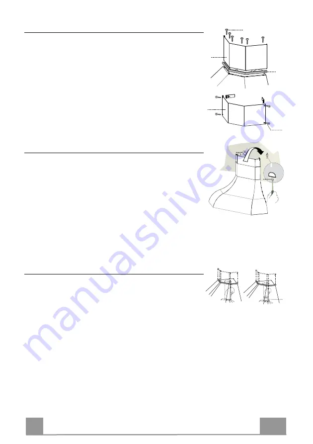
Montaje de la chimenea 

Chimenea inferior 

•  Colocar el Perfil de madera 

20

 (opcional) entre el Cuerpo de la 

Campana y la Chimenea 

•  Sujetar desde la parte superior, la parte inferior de la Chimenea 

y el Cubrecable  al Cuerpo de la Campana con 6 Tornillos 

12g


en dotación. 

Chimenea superior 

•  Ensanchar  ligeramente  las  dos  faldas  laterales,  engancharlas 

detrás de la brida 

7.2.1

 y dejarlas volver a su posición inicial. 

•  Fijar a los lados de las bridas con los 4 tornillos 

12c

 en dota-

ción. 


20

12g

2.2

2.1

12c

Montaje del cuerpo de la campana 

Si  el  instalador  lo  desea,  se  puede  colocar  un  angular  de  cierre 

con  el  muro  atornillándolo  en  la  parte  posterior  de  la  campana 
usando tres tornillos 

12b

 incluídos en la dotación. 

•  Regular los dos tornillos 

Vr

, de las abrazaderas 

11a

, sin apre-

tarlos completamente. 

•  Enganchar el cuerpo de la campana en las 2 abrazaderas 

11a

•  Quitar los Filtros Antigrasa maniobrando en las manillas. 
•  Ajustar los tornillos 

Vr 

para nivelar el Cuerpo de la Campana. 

•  Sujetar definitivamente la campana a la pared usando los dos 

orificios de seguridad situados en la parte inferior interior de la 
campana (tacos 

11

 + tornillos 

12a

). 


11a

Vr


Conexiones 

SALIDA DEL AIRE VERSIÓN ASPIRANTE 

Para la instalación de la versión aspirante, conectar la campana al 

tubo de salida mediante un tubo rígido o flexible de ø150 o 120 
mm, a discreción del instalador. 

•  Para la conexión con el tubo de ø120 mm, introducir la brida de 

reducción 

en la salida del cuerpo de la campana. 

•  Fijar  el  tubo  con  abrazaderas  adecuadas.  Este  material  no  se 

proporciona en dotación. 

•  Quitar los filtros antiolor al carbón activo. 


ø 150

ø 120

9


Summary of Contents for WEST ANGOLO BIANCO SC

Page 1: ...Instructions Manual Manuel d Instructions Bedienungsanleitung Manual de instrucciones Instrukcja Obs ugi...

Page 2: ...CTERISTIQUES 18 INSTALLATION 20 UTILISATION 23 UTILISATION ENTRETIEN 24 INHALTSVERZEICHNIS SICHERHEITSINFORMATIONEN 26 CHARAKTERISTIKEN 29 MONTAGE 31 BEDIENUNG 34 BEDIENUNG WARTUNG 35 NDICE INFORMACI...

Page 3: ...3 3 SPIS TRE CI INFORMACJE DOTYCZ CE BEZPIECZE STWA 70 W A CIWO CI TECHNICZNE 73 INSTALACJA 75 U YTKOWANIE 78 U YTKOWANIE KONSERWACJA 79 PL...

Page 4: ...eight please refer to the paragraphs on working dimensions and installation If the instructions for installation for the gas hob specify a greater distance this must be respected Check that the mains...

Page 5: ...to be adopted for fume discharging it is important to closely follow the regulations provid ed by the local authorities WARNING Before installing the Hood remove the protective films Use only screws a...

Page 6: ...ack into the room The symbol on the product or on its packaging indicates that this product may not be treated as household waste Instead it shall be handed over to the applicable collection point for...

Page 7: ...e 150 120 mm 10 1 Shelf Frame optional 20 1 Wooden Profile optional 30 1 Lower corner spacer Ref Q ty Installation Components 7 2 1 4 Chimney Fixing Brackets 11 6 Wall Plugs 11a 2 Wall Plugs SB 12 10...

Page 8: ...EN 8 8 Dimensions...

Page 9: ...ce Mark a reference point at 1 2 mm below the ceiling or top limit and at 341 mm from the corner of the wall as shown Repeat the operation for the opposite side and check levelling Drill at the points...

Page 10: ...ovided Adjust the two screws Vr on brackets 11a to a minimum Hook the hood canopy onto the two brackets 11a Remove the filters one at a time after disconnecting the rela tive fastening elements From i...

Page 11: ...pe 150 mm to be selected by the installer Fix the pipe in position using sufficient pipe clamps not sup plied Fix the directional grille 8 on the recirculation air outlet using the 2 screws 12e 2 9 x...

Page 12: ...ts the operating speed of the extractor 1 Low speed used for a continuous and silent air change in the presence of light cooking vapour 2 Medium speed suitable for most operating conditions given the...

Page 13: ...e filters taking care not to bend them Allow them to dry before refitting When refitting the filters make sure that the handle is visible on the outside Activated charcoal filter Recirculation version...

Page 14: ...HSGSB C UB 28 220 240 E14 28 E14 230 85x25 HDG 28 230 E14 25 20 G4 12 33 x 9 HSG C UB 20 12 G4 35 GU10 230 51 x 50 7 HAGS 35 230 GU10 51 40 50 GU10 230 51 x 50 7 HAGS 35 230 GU10 51 20 20 GU4 12 40 x...

Page 15: ...r inf rieure voir le paragraphe concernant les dimensions de travail et l installation Si les instructions d installation du plan de cuisson gaz sp cifient une distance sup rieure celle indiqu e ci de...

Page 16: ...par les autorit s locales AVERTISSEMENT Avant d installer la hotte retirer les films de protection Utilisez exclusivement des vis et des petites fournitures du type adapt pour la hotte AVERTISSEMENT...

Page 17: ...x appareils qui vacuent l air uniquement dans la pi ce Le symbole marqu sur le produit ou sur son emballage indique que ce produit ne peut pas tre limin comme d chet m nager normal Lorsque ce produit...

Page 18: ...9 1 Flasque de R duction 150 120 mm 10 1 Cadre de la Tablette si fournie 20 1 Profil en bois si fourni 30 1 Bouchon d angle inf rieur R f Q t Composants pour l installation 7 2 1 4 Brides Fixation Che...

Page 19: ...FR 1 9 19 Encombrement...

Page 20: ...rquer comme indiqu un point de r f rence 1 2 mm en dessous du plafond ou de la limite sup rieure et 341 mm de l angle de la paroi r p ter cette op ration du c t oppos et v rifier le nivellement Percer...

Page 21: ...eux vis Vr des brides 11a en d but de course Accrocher le corps de la hotte aux 2 brides 11a Enlever les filtres graisse en intervenant sur les poign es sp cialement pr vues Depuis l int rieur du corp...

Page 22: ...au moyen d un tube rigide ou flexible de 150 mm dont le choix sera effectu par l installateur Fixer le tube par des colliers appropri s Le mat riau n cessai re n est pas fourni Fixer la Grille orient...

Page 23: ...insi subdivis es 1 Vitesse minimale pour un rechange d air permanent particuli rement silencieux en cas de faibles vapeurs de cuisson 2 Vitesse moyenne pour la plupart des conditions d utilisation tan...

Page 24: ...s filtres en vitant de les plier et les laisser s cher avant de les remonter Remonter les filtres en veillant ce que la poign e reste vers la partie visible externe Filtre anti odeur Version filtrante...

Page 25: ...14 220 240 104 x 35 HSGSB C UB 28 220 240 E14 28 E14 230 85x25 HDG 28 230 E14 25 20 G4 12 33 x 9 HSG C UB 20 12 G4 35 GU10 230 51 x 50 7 HAGS 35 230 GU10 51 40 50 GU10 230 51 x 50 7 HAGS 35 230 GU10 5...

Page 26: ...ige Modelle k nnen auch niedriger installiert werden siehe Absatz Installation Sollten die Installationsanweisungen des gasbetriebenen Kochfelds einen gr eren Abstand als oben angegeben vorsehen ist d...

Page 27: ...hen Beh rden streng einzuhalten WARNUNG Bevor die Haube installiert wird die Schutzfolien abziehen Nur f r die Abzugshaube geeignete Schrauben und Kleinteile verwenden WARNUNG Die mangelnde Verwendung...

Page 28: ...n sein gilt nicht f r Ger te die nur Luft in den Raum ablassen Schutzschild bei Rissbildung ersetzen Das Symbol am Produkt oder auf der Verpackung weist darauf hin dass das Ger t nicht als normaler Ha...

Page 29: ...duzierflansch 150 120 mm 10 1 Bordleiste option 20 1 Holzprofil option 30 1 Eckf rmige untere Abdeckung Pos St Montagekomponenten 7 2 1 4 Befestigungsb gel Kamin 11 6 B gel 11a 2 B gel SB 12 10 12a 6...

Page 30: ...DE 3 0 30 Platzbedarf...

Page 31: ...f gen und festschrauben Wie gezeigt einen Bezugspunkt 1 2 mm unterhalb der Decke oder oberen Begrenzung und 341 mm von der Wandecke kennzeichnen diesen Vorgang an der gegen berliegenden Seite wiederho...

Page 32: ...den Schrauben Vr der B gel 11a so regulieren dass sie nur bis zum Gewindebeginn eingeschraubt sind Den Haubenk rper bei den 2 B geln 11a einhaken Die Fettfilter mit den entsprechenden Griffen demontie...

Page 33: ...sen mit der Deckenplatte verbinden Das Rohr mit geeigneten Rohrschellen fixieren Das hierzu erforderliche Material wird nicht mitgeliefert Das Luftleitgitter 8 mit Hilfe von 2 der mitgelieferten Schra...

Page 34: ...geringste Gebl sestufe diese Stufe ist f r einen st ndigen und besonders leisen Luftaustausch bei geringer Kochdunstentwicklung geeignet 2 mittlere Gebl sestufe eignet sichaufgrund des guten Verh ltni...

Page 35: ...erbiegen und vor der Remontage trocknen lassen Bei der Remontage ist darauf zu achten dass sich der Griff auf der sichtbaren Au enseite befindet Geruchsfilter Umluftbetrieb Sie k nnen weder gewaschen...

Page 36: ...C UB 28 220 240 E14 28 E14 230 85x25 HDG 28 230 E14 25 20 G4 12 33 x 9 HSG C UB 20 12 G4 35 GU10 230 51 x 50 7 HAGS 35 230 GU10 51 40 50 GU10 230 51 x 50 7 HAGS 35 230 GU10 51 20 20 GU4 12 40 x 35 HRG...

Page 37: ...altura inferior v ase la secci n sobre dimensiones de trabajo e instalaci n Si en las instrucciones de montaje de la placa de cocci n a gas se indica una distancia mayor que la indicada anteriormente...

Page 38: ...os es importante cumplir escrupulosamente las normas establecidas por las autoridades locales ADVERTENCIA Retire la pel cula protectora antes de instalar la campana Utilice nicamente tornillos y herra...

Page 39: ...aire en el local El s mbolo en el producto o en su embalaje indica que este producto no debe desecharse como residuo dom stico normal Tenga en cuenta que el producto a eliminar debe recogerse en un pu...

Page 40: ...de reducci n 150 120 mm 10 1 Cornisa repisa opcional 20 1 Perfil de madera opcional 30 1 Tap n a ngulo Inferior Ref Cant Componentes de Instalaci n 7 2 1 4 Brida de fijaci n chimenea superior 11 6 Ta...

Page 41: ...ES 4 1 41 Dimensiones...

Page 42: ...ar como se indica un punto de referencia a 1 2 mm del techo o l mite superior y a 341 mm del ngulo de la pared repertir la operaci n en la parte opuesta controlando la nivela ci n Agujerear con una pu...

Page 43: ...en la dotaci n Regular los dos tornillos Vr de las abrazaderas 11a sin apre tarlos completamente Enganchar el cuerpo de la campana en las 2 abrazaderas 11a Quitar los Filtros Antigrasa maniobrando en...

Page 44: ...ido o flexible de 150 mm a discreci n del instalador Fijar el tubo con abrazaderas adecuadas Este material no se proporciona en dotaci n Fijar la rejilla de direcci n 8 en la salida del aire reciclado...

Page 45: ...o 1 Velocidad m nima indicada para un recambio de aire continuo muy silencioso en presencia de pocos vapores de cocci n 2 Velocidad media indicada para la mayor parte de las condiciones de uso gracias...

Page 46: ...ue se doblen y dejarlos secar antes de volverlos a montar Montar los filtros prestando atenci n en mantener la manija hacia la parte visible exterior Filtros antiolor Versi n filtrante No se pueden la...

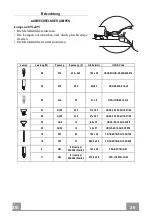
Page 47: ...uillo Voltaje V Dimensi n mm C digo ILCOS 28 E14 220 240 104 x 35 HSGSB C UB 28 220 240 E14 28 E14 230 85x25 HDG 28 230 E14 25 20 G4 12 33 x 9 HSG C UB 20 12 G4 35 GU10 230 51 x 50 7 HAGS 35 230 GU10...

Page 48: ...GR 4 8 48 650 mm 120 mm...

Page 49: ...GR 4 9 49 0 04 mbar 8...

Page 50: ...GR 5 0 50...

Page 51: ...8 1 125 mm 9 1 150 120 mm 10 1 20 1 30 1 7 2 1 4 11 6 11a 2 SB 12 10 12a 6 4 2 x 44 4 12b 3 2 9 x 6 5 12c 4 2 9 x 9 5 12e 2 2 9 x 9 5 12n 7 3 5 x 16 12g 6 3 5 x 19 1 12g 30 12b 20 8 9 12e 12c 2 1 2 1...

Page 52: ...GR 5 2 52...

Page 53: ...GR 5 3 53 458 650 min 356 356 341 341 11a 185 2 3 12a 11 650 mm min 356 mm 458 mm 12 mm 11a 1 2 mm 341 mm 8 mm 11 12a 4 2 x 44 4 185 mm 341 mm 8 mm 11 12a 4 2 x 44 4...

Page 54: ...GR 5 4 54 20 6 12g 7 2 1 2 12c 20 12g 2 2 2 1 12c 12b Vr 11a 11a Vr 11 12a 11a Vr o150 120 mm o120 mm 9 150 120 9...

Page 55: ...GR 5 5 55 10 4 12n 3 5 x 16 10 12f 1 12n 10 150 150 8 2 12e 2 9 x 9 5 8 12e 150 3 mm...

Page 56: ...GR 5 6 56 1 1 0 1 0 2 3 L M V L M V 1 2 3...

Page 57: ...GR 5 7 57 2 4 A B A B...

Page 58: ...0 51 x 50 7 HAGS 35 230 GU10 51 40 50 GU10 230 51 x 50 7 HAGS 35 230 GU10 51 20 20 GU4 12 40 x 35 HRGS 20 12 GU4 35 30 20 GU5 3 12 46 x 51 HRGS 20 12 GU5 3 50 10 16 G13 95 720 x 26 FD 16 40 1B E G13 2...

Page 59: ...RU 5 9 59 650 I 120...

Page 60: ...RU 6 0 60 0 04 8...

Page 61: ...RU 6 1 61...

Page 62: ...2 1 8 1 125 9 1 150 120 10 1 20 1 30 1 7 2 1 4 11 6 11a 2 SB 12 10 12a 6 4 2 x 44 4 12b 3 2 9 x 6 5 12c 4 2 9 x 9 5 12e 2 2 9 x 9 5 12n 7 3 5 x 16 12g 6 3 5 x 19 1 12g 30 12b 20 8 9 12e 12c 2 1 2 11a...

Page 63: ...RU 6 3 63...

Page 64: ...RU 6 4 64 458 650 min 356 356 341 341 11a 185 2 3 12a 11 650 356 458 12 11 1 2 341 8 11 12a 4 2 x 44 4 185 341 8 11 12a 4 2 x 44 4...

Page 65: ...RU 6 5 65 20 6 12g 7 2 1 2 12c 20 12g 2 2 2 1 12c 12b Vr 11a 11 Vr 11 12 11a Vr 150 120 120 9 150 120 9...

Page 66: ...RU 6 6 66 10 4 12n 3 5 x 16 10 12f 1 12n 10 150 150 8 2 12e 2 9 x 9 5 8 12e 150 3...

Page 67: ...RU 6 7 67 1 1 0 1 0 2 3 L M V L M V 1 2 3...

Page 68: ...RU 6 8 68 2 4 A B...

Page 69: ...U10 230 51 x 50 7 HAGS 35 230 GU10 51 40 50 GU10 230 51 x 50 7 HAGS 35 230 GU10 51 20 20 GU4 12 40 x 35 HRGS 20 12 GU4 35 30 20 GU5 3 12 46 x 51 HRGS 20 12 GU5 3 50 10 16 G13 95 720 x 26 FD 16 40 1B E...

Page 70: ...si co najmniej 650 mm niekt re modele mog zosta zainstalowane ni ej patrz odpowiedni rozdzia zawieraj cy wymiary robocze i monta owe Je li instrukcja instalacji kuchenki gazowej wskazuje na potrzeb za...

Page 71: ...ych odprowadzania spalin ustanowionych przez w adze lokalne OSTRZE ENIE przed przyst pieniem do instalacji okapu nale y zdj folie ochronn U ywa wy cznie rub oraz osprz tu typu odpowiedniego dla danego...

Page 72: ...wietrze z pomieszczenia Symbol znajduj cy si na urz dzeniu lub na jego opakowaniu oznacza e nie wolno danego urz dzenia wyrzuca razem ze zwyk ymi odpadami domowymi Zu yty produkt nale y przekaza do ce...

Page 73: ...a kierunkowa 125 mm 9 1 Ko nierz redukcyjny 150 120 mm 10 1 Ramka szafki opcja 20 1 Profil drewniany opcja 30 1 Za lepka naro nika dolnego Odn Il Elementy monta owe 7 2 1 4 Elementy monta owe komina g...

Page 74: ...PL 7 4 74 Wymiary...

Page 75: ...ano na rysunku punkt odniesienia w odleg o ci 1 2 mm od sufitu lub na wysoko ci granicznej oraz 341 mm od naro nika ciany powt rzy t czynno po przeciwnej stronie sprawdzaj c wypoziomowanie Wywierci ot...

Page 76: ...rub 12b Na pocz tku wyregulowa dwie ruby Vr wspornik w 11a Za o y korpus okapu na 2 wsporniki 11a Wyci gn filtry jeden po drugim odczepiaj c odpowiednie zaczepy Wykorzysta ruby Vr do wypoziomowania ko...

Page 77: ...nej 150 mm wyb r pozostaje po stronie instalatora Zamocowa rur z odpowiednimi opaskami Konieczne materia y nie znajduj si w zestawie Przykr ci kratk kierunkow 8 przy pomocy 2 rub 12e 2 9 x 9 5 znajduj...

Page 78: ...i pracy wentylatora 1 Pr dko niska przewidziana do sta ej i cichej wentylacji kuchni przy niewielkiej ilo ci opar w 2 Pr dko rednia w a ciwa dla wi kszo ci panuj cych podczas gotowania warunk w zapewn...

Page 79: ...a filtr w podczas mycia Przed ponownym monta em wewn trz okapu upewni si czy s ca kowicie suche Wk adaj c filtry z powrotem do okapu nale y zwr ci uwag aby zosta y poprawnie zamontowane uchwytem do ze...

Page 80: ...HSGSB C UB 28 220 240 E14 28 E14 230 85x25 HDG 28 230 E14 25 20 G4 12 33 x 9 HSG C UB 20 12 G4 35 GU10 230 51 x 50 7 HAGS 35 230 GU10 51 40 50 GU10 230 51 x 50 7 HAGS 35 230 GU10 51 20 20 GU4 12 40 x...

Page 81: ......

Page 82: ......

Page 83: ......

Page 84: ...991 0432 061_ver5 190426 D000000002611_02...

Reviews: