12
• Insert the cables into the safety knobs
(c)
with the thread at the top (Fig.12).
• Insert the cables into the cable clamp screws
(b)
(Fig.12).
• Pass the cables through the slots in the threaded pawls
(a)
and screw the
cable locking screws
(b)
to the pawls themselves (Fig.13).
• When the operation has been completed the result must be as shown in
the figure for all 4 cables (Fig.13).
• At this point we have all 4 cables connected to the plate.
Bring the cables under tension by pushing them upwards so that
they slide inside the cable clamp screw and slide out of the slot in the
threaded pawl.
This is possible because the cable clamp screw has a system that, if
mounted properly, allows the cables to slide inside it in one direction
only, and prevents it from sliding in the other
direction.
Attention, the cables all have the same length to facilitate the opera-
tion of the final level. The front left cable must not be slacker than the
others.
12
13
14
B
C
Summary of Contents for Zoom IS 16 SS
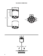
Page 6: ...6 RANGEHOOD DIMENSIONS 57 8 43 16 43 16 43 16 43 16 161 8 16 15 16 Max 515 8 Min 24 Min 30...
Page 18: ...18 Wiring Diagram...
Page 24: ...24 DIMENSIONS DE LA HOTTE 57 8 43 16 43 16 43 16 43 16 161 8 16 15 16 Max 515 8 Min 24 Min 30...
Page 36: ...36 Sch ma de c blage...
Page 54: ...54 Diagrama de cableado...
Page 58: ......
Page 59: ......

