INSTRUCTIONS F330
15
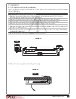
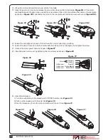
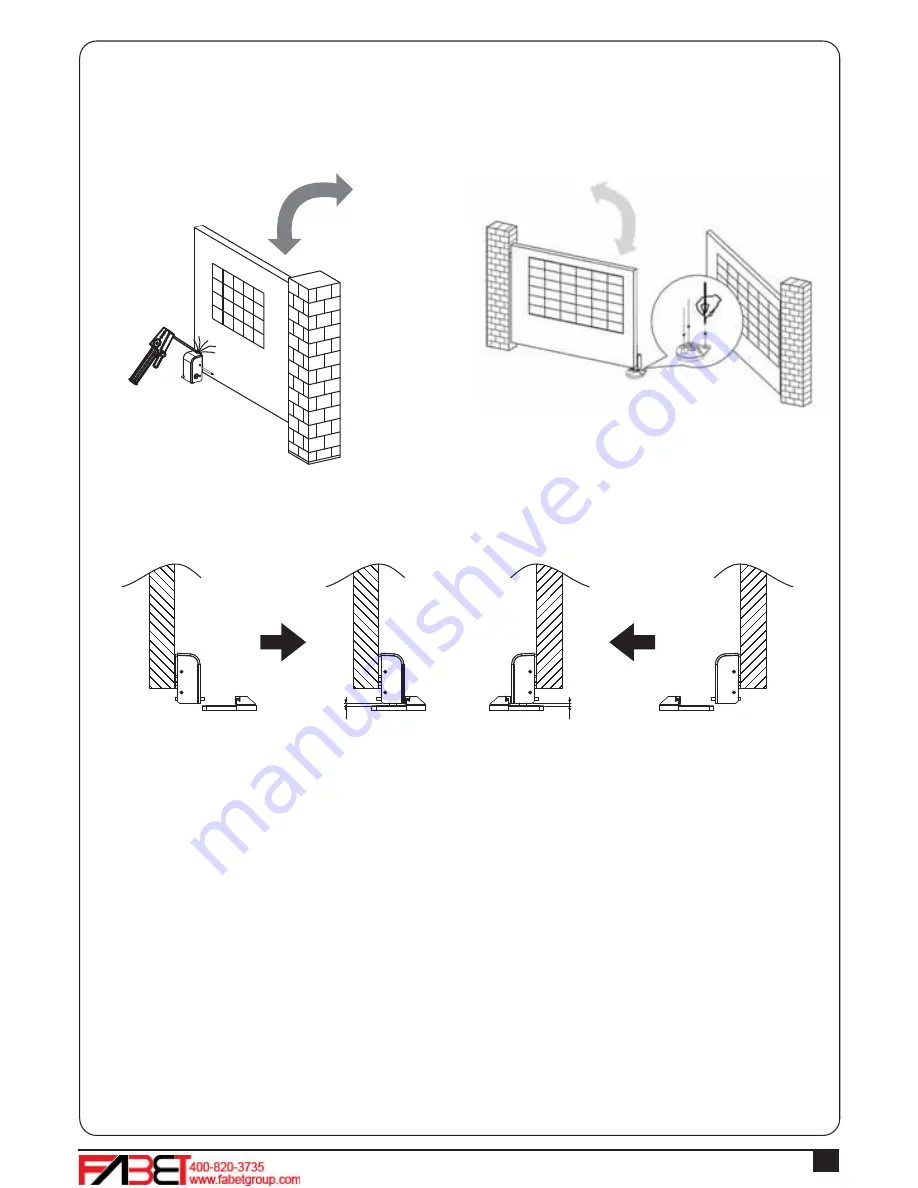
2). Weld the back plate of the electric latch to the surface on the master gate. See
Figure 3.3.7 (8).
Please avoid melting the wires by the heat of the fixed plate.
Figure3.3.7(8)
For the gate opened inward.
Figure3.3.7(9)
For the gate opened Outward.
3). The gap between the bottom of electric latch and the stopper should be less than 7mm. See
Figure 3.3.7 (10)
4). Connect the wires of the electric latch to the terminal LAT(+) and LAT(-) on the PCB.
Figure3.3.7(10)
For the gate opened inward.
Figure3.3.7(11)
For the gate opened Outward.
7mm
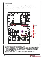
7mm
Summary of Contents for F330
Page 2: ......
Page 19: ...INSTRUCTIONS F330 17 Transformer Figure 3 3 8 5 12V 12V 12V ...
Page 28: ......

