background image

INSTRUCTIONS F330

19

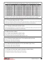
4.1.4 Photocells Adjustment (Dip 7.Photo)

4.1.5 Flashing Light Adjustment (Dip 8.Light)

4.2.1 Electric Latch Adjustment (Dip 5.Latch)

4.2.2 Slowdown Speed Adjustment of The Gear Motors (Dip 6.Slow)

4.2.3 Operation Speed Adjustment of The Gear Motors (Dip 7.Fast)

4.2.4 Single and Dual Gate Operation Adjustment (Dip 8.Ds/Set)

4.2 SW2 Dip Switch Setting

4.1.3 Gate Auto-close Adjustment (Dip 4.Auto 3, Dip 5.Auto 2 & Dip 6.Auto 1)

Dip switch 6 OFF

Dip switch 6 ON

Dip switch 6 OFF

Dip switch 6 ON

Dip switch 6 OFF

Dip switch 6 ON

Dip switch 6 OFF

Dip switch 6 ON

Dip Switch 5 OFF

Dip Switch 5 OFF

Dip Switch 5 ON

Dip Switch 5 ON

Dip Switch 5 OFF

Dip Switch 5 OFF

Dip Switch 5 ON

Dip Switch 5 ON

Dip Switch 4 OFF

Dip Switch 4 OFF

Dip Switch 4 OFF

Dip Switch 4 OFF

Dip Switch 4 ON

Dip Switch 4 ON

Dip Switch 4 ON

Dip Switch 4 ON

No auto-close

3 sec.

10 sec.

20 sec.

40 sec.

60 sec.

120 sec.

300 sec.

Auto-close 1 

                      Auto-close 2 

                Auto-close 3                           Effect

ON: When encountering any obstacles, the gates will stop during opening phase ; stop and reverse during closing phase.

OFF: The gate will keep moving when encountering any obstacles during closing and opening phases.

ON: The flashing light blinks for 3 seconds before the gate moves, and blinks simultaneously during the movement.

OFF: The flashing light blinks and the gate moves simultaneously.

ON: The electric latch functions when dip switch is set to “ON”.

OFF: The electric latch does not function when dip switch is set to “OFF”.

ON: The speed is 70% output of the full speed.

OFF: The speed is 50% output of the full speed.

ON: The speed is 100% output of the full speed.

OFF: The speed is 80% output of the full speed.

ON: Dual Gates operation in system learning and normal operation.

OFF: Single Gate operation in system learning and normal operation.

Note: Auto-close mode activates when the gates move to the end position or stopped manually. If the transmitter, 

push button, or the key selector is activated before the auto-close counting, the gate will close immediately.

Summary of Contents for F330

Page 1: ...Flashing Light Control box Push Button Gate 2 Gate 1 FOR RESIDENTIAL F330 SWING GATE OPENERS 24V DC GEAR MOTOR USER MANUAL ߆ԇࢽি 400 820 3735 ৠ www fabetgroup com ...

Page 2: ......

Page 3: ...down Adjustment Dip 1 S F Set 4 1 2 Over current Adjustment Dip 2 Over2 Dip 3 Over1 4 1 3 Gate Auto close Adjustment Dip 4 Auto 3 Dip 5 Auto 2 Dip 6 Auto 1 4 1 4 Photocells Adjustment Dip 7 Photo 4 1 5 Flashing Light Adjustment Dip 8 Light 4 2 SW2 Dip Switch Setting 4 2 1 Electric Latch Adjustment Dip 5 Latch 4 2 2 Slowdown Speed Adjustment of The Gear Motors Dip 6 Slow 4 2 3 Operation Speed Adjus...

Page 4: ... installing the gate automated system and confirm the gates are appropriate for the application Do not let children operate or play with the gate automated system Do not cross the path of the gate automated system when operating Please keep all the control devices and any other pulse generator away from children to avoid the gate automated system being activated accidentally Do not make any modifi...

Page 5: ...gate automation system 2 3 Description of Devices A B C D E F330 includes the accessories shown in Figure 2 Please check the accessories the same as the package provided Attention Some accessories of F330 are not included due to local regulations or customized order A 2 F330 electromechanical gear motors with mounting brackets B 2 release keys C 1 pair of PH 1photocells one TX and one RX D 2 PR 1 ...

Page 6: ...3 3 PH 1 Photocells The pair of PH 1 photocells has to be installed on the wall and connected to the control panel The function of the photocells is to detect the obstacles found on the optical axis between the transmitter TX and the receiver RX 2 3 4 PR 1 Radio Transmitter PR 1 radio transmitter is used for the remote control of the gate movement To use the transmitter press and hold the button f...

Page 7: ...itter PKS 1 key selector is supplied with two keys 2 3 7 PPB 1 Push Button The PPB 1 push button is used for opening the gate indoors without the radio transmitter 3 1 Notes of Motors in Operation The F330 gate openers are applicable to per leaf of 4 0 meters in width and 350 kg in weight which can be opened up to 120 degrees primarily for residential use where the performance shall be influenced ...

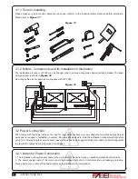
Page 8: ...d 7m long which requires very low voltage that no professionally trained personnel is required in installation however the users are advised to read the installation manual carefully before going for it After getting to know all accessories and their positions suggest starting from cable conduit arrangement to prevent the cables from being broken or damaged 3 2 Power Connection 1 The installation ...

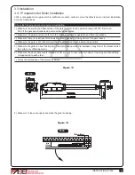
Page 9: ...conform to the criteria of automatic operation and force regulations 3 Make sure there is no serious friction existing in the opening or closing travel of the gate leaves 4 Make sure the gate is at horizontal level that the gate will not move aside at any position 5 Make sure the gate can bear the impact of the motor torque when it is installed on any hole of the bracket which the surface is suffi...

Page 10: ... 14 The value of B can be calculated from the value of A and the leaves opening angle Ex If A 160mm with the leaves opening angle of 100 degrees then the value of B is approximate 190mm Please make sure B and A are similar or the same in value that the leaves can be operated smoothly also to reduce the burden of the motor 9 If the gate is OPENED OUTWARD please leave at least 70mm between the post ...

Page 11: ...sed position Figure 23 Figure 24 10 Refer to Figure 23 the distance between front plate of the motor and rear plate is 798mm F330 the difference in height is 2 5mm F330 11 Clamp and fix the motor front plate on the door temporarily 7 Refer to the distance of B in Figure 17 place the rear plate in the correct position on the mounting surface Inspect if the distance is proper as shown in Figure 23 i...

Page 12: ... the end until the screw holes of the motor end matches the holes on the rear plate as shown in Figure 25 1 and fasten the motor to the rear plate with bolt and screw as shown in Figure25 2 21 Connect the motor power cable as shown in Figure27 22 Close the gear motor cover by tightening the two screws as shown in Figure28 23 Gear Motor Release 1 Turn the round plate on the release part to OPEN pos...

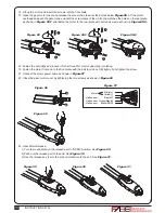
Page 13: ... three holes at the bottom and mark the points by the holes as reference 6 Drill the holes in the wall and fix the bottom to the wall by three screws See Figure 3 3 3 5 7 Connect the electric wires to the terminals as shown in Figure 3 3 3 6 and it s not required to distinguish any polarity The terminals can be removed for connecting the wires easily 8 Turn the key and insert the shell on the bott...

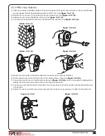
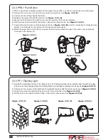
Page 14: ... of about 100cm so that it could be used by most people 2 Remove the round cover A by prizing it out with a screwdriver See Figure 3 3 4 1 3 Unscrew the two screws beside the button 4 Separate the upper shell with the bottom See Figure 3 3 4 2 5 Breach the three holes at the bottom and mark the points by the holes as reference 6 Drill the holes in the wall and fix the bottom to the wall by three s...

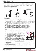
Page 15: ... a new one 7 4 Tighten the three screws A B C of the flashing light cover Figure 3 3 5 5 Figure 3 3 5 6 Figure 3 3 5 7 Figure 3 3 6 1 Figure 3 3 6 2 Figure 3 3 6 3 A B C 3 Wiring connection TX Connect terminals 1 and 2 on the transmitter with the terminals GND and 24V on the PC200 PCB RX Connect terminals 1 2 and 4 on the receiver with the terminals GND 24V and phot1 on the PC200 PCB And use an ex...

Page 16: ...ctric Latch If the gate is opened outward 1 If the gate is opened outward please change the spring inside and screw it in the different place See Figure 3 3 7 4 Figure 3 3 7 5 Figure 3 3 7 6 Figure 3 3 7 7 Note If the gate is opened outward place the stopper in opposite direction 3 Drill the 3 marked points and then securely attach the stopper to the ground with screws and washers See Figure 3 3 7...

Page 17: ...ed plate Figure3 3 7 8 For the gate opened inward Figure3 3 7 9 For the gate opened Outward 3 The gap between the bottom of electric latch and the stopper should be less than 7mm See Figure 3 3 7 10 4 Connect the wires of the electric latch to the terminal LAT and LAT on the PCB Figure3 3 7 10 For the gate opened inward Figure3 3 7 11 For the gate opened Outward 7mm 7mm ...

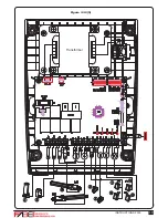
Page 18: ...M1 and Yellow to the M1 Connect the hall sensor wires red green and black to the terminals 5V S1 and GND M2 Connect the motor wire White to the terminals M2 and Yellow to the M2 Connect the hall sensor wires red green and black to the terminals 5V S2 and GND Notes For gates opened outward M1 Connect the motor wire Yellow to the terminals M1 and White to the terminals M1 M2 Connect the motor wire Y...

Page 19: ...INSTRUCTIONS F330 17 Transformer Figure 3 3 8 5 12V 12V 12V ...

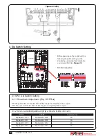
Page 20: ...OFF Dip Switch 2 ON Dip Switch 2 ON 2A 3A 4A 5A OVER1 OVER2 Current Amp 4 Dip Switch Setting Figure 3 3 8 6 Before powering on the control unit the following dip switch setting must be decided by gate weight and installation environment first See Figure 32 NC No Connection ON The gear motors do not slow down before the gates completely close or open OFF The gear motors slow down before the gates c...

Page 21: ...ec Auto close 1 Auto close 2 Auto close 3 Effect ON When encountering any obstacles the gates will stop during opening phase stop and reverse during closing phase OFF The gate will keep moving when encountering any obstacles during closing and opening phases ON The flashing light blinks for 3 seconds before the gate moves and blinks simultaneously during the movement OFF The flashing light blinks ...

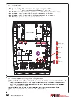
Page 22: ...ess and hold the S3 button on the PCB for three seconds C One radio receiver can be memorized with 200pcs of transmitters LED1 System Learning LED1 blinks once when single gate learning is completed LED1 blinks twice when dual gate learning is completed LED2 RF If the switch of the transmitter key selector or the push button is activated LED2 will be on LED3 Photocells 1 LED3 will be on when the f...

Page 23: ...nd the master gate closes 3 seconds after the slave gate closes 4 6 Gate Operation Press the button A on the transmitter for dual gate operation Press the button B on the transmitter for single gate operation in either single gate or dual gate installation 4 7 Gate moving Logic 4 8 Advanced Operation of the Transmitter A In gate opening phase The gates stop if the transmitter push button key selec...

Page 24: ... the gate opening and closing Check the wiring connection of the batteries 1 Check if LED3 or 4 is ON 2 Check if the voltage of the batteries is below 22V 3 Check if LED1 is ON 4 Make sure all the wiring connections are firmly connected to the terminals on the PCB 5 Make sure the fuse is workable Make sure the wiring connection of the hall sensor is firm Make sure the connecting terminals of the A...

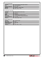
Page 25: ...perating Temperature Protection class Dimension Through beam 30 meters 100ms AC DC 12 24V 20ʨ 60ʨ IP66 59mm 87mm 38mm 6 4 PKS 1 Key Selector Application Installation Operating Temperature Dimension For outdoor use Wall mounted vertically 20ʨ 50ʨ 85mm 60 5mm 40 5mm 6 5 PPB 1 Push Button Application Installation Operating Temperature Dimension For outdoor use Wall mounted vertically 20ʨ 50ʨ 85mm 60 ...

Page 26: ...V with one CR2032 button type lithium battery 20ʨ 50ʨ 71 5mm 33mm 14mm 6 8 PEL 1 Electric Latch Application Power Supply Operating Temperature Operating Current Dimension For locking the gate 24Vdc 20ʨ 50ʨ 5A 61mm 55mm 120mm 6 6 PF 1 Flashing Light Application Lamp Operating Temperature Installation Dimension For warning purpose during leaves movement 24Vdc Halogens bulb 20ʨ 50ʨ horizontally or ve...

Page 27: ...ct has been tasted for CE marking according to the following European Directives 2006 42 EC Machinery Directive Comply with the following Standards EN 301489 1 V1 8 1 2008 EN 301489 3 V1 4 1 2002 EN 300220 1 V2 1 1 2006 EN 300220 2 V2 1 2 2007 EN 60335 1 2002 A11 2004 A1 2004 A12 2006 A2 2006 A13 2008 EN 60335 2 103 2003 EN 62233 2008 EN 12445 2001 EN 12453 2001 And also declare that the machinery...

Page 28: ......
Reviews: