FabiaTech Corporation
58
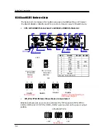
RS485 and RS422 Hardware Setup
The Serial port 2 is designed for multiple proposes. Use BIOS setting or JP4 select
the RS-232, RS422 or RS-485, and JP11 provide terminator select of RS-485 mode.
JP11 & JP4: RS485 Terminal Select and RS422 or RS485 Port Selected
1
2
Antenna
4
2
3
1
/
+
-
DC12~24V
ON
OFF
JP5, JP6, JP7 & JP8: Select Power Source Jumper Select
All Serial ports provide power source will driver the “RI” signal pin if JP8, JP6 for
COM3, COM4 and JP7, JP5 for COM1, COM2 were located on the power output
position.
DB-9
RS-232
RS-422 RS-485
1 -DCD
6 -DSR
2 RXD RX-
485-
7 -RTS TX-
3 -TXD RX+
485+
8 -CTS TX+
4 -DTR
9 -RI
5 Ground
Metal Case
Ground
*Note: Changing the setting in
BIOS setup program
3
2
1
Pin 1,2 Close:
Terminator
Enabled
JP11
Pin 2,3 Close:
Terminator
Disable
Default
Factory Preset
+12V
JP5/JP6/JP7/JP8
RI
+5V
6
5
4
3
1
2
6
5
4
3
1
2
6
5
4
3
1
2
3
2
1
RS-232
Factory Preset
5
2
6
1
JP4
RS-485
5
2
6
1
RS-422
5
2
6
1
Disable
5
2
6
1
Summary of Contents for Fanless Series FX5403
Page 6: ...vi Appendix 59 Dimension 59 ...
Page 7: ...vii ...
Page 10: ...FabiaTech Corporation 3 Layout 1 2 Antenna 4 2 3 1 DC12 24V ON OFF ...
Page 13: ...FabiaTech Corporation 6 ...
Page 23: ...FabiaTech Corporation 16 ...
Page 51: ...FabiaTech Corporation 44 ...


