Version 1.4
FX5401 User’s Quick Reference
Page 2/2
©2002 FabiaTech Corp.
D. Serial Port Connectors (
9-pin D-sub, Male
)
E. Parallel Port Connector (
25-pin D-sub, Female
)
This 25-pin D-sub female connector is a standard-type parallel port connector.
F. CRT Connector (
15-pin D-sub, Female
)
G. USB
Connectors
The upper port is USB#1 and the lower port is the USB#2.
H. IDE HDD/CDROM and DiskOnModule Connectors (
IDE2, IDE3
and
IDE4
on FB4626 adapter
board)
IDE2 (beside the CF socket) is used to connect a 2.5" HDD directly. IDE3 is used to plug-in a
DiskOnModule (DOM) flash disk.
Note that 2.5" HDD and DOM can not exist simulatously
.
IDE4 is reserved for user to connect a CDROM drive for installing OS to 2.5" HDD or DOM. You can
order the specify CDROM cable or FB4613 (2.5" to 3.5" adapter board) from FabiaTech.
Please set the occupied devices of 2.5" HDD/DOM, CDROM and CompactFlash (see jumper JP2)
separately.
Note that only 2 of these 4 devices can be used simulatously
.
I.
Audio Connectors and Jumper (3-term Ear-Jet and
JP3
on FB4626 adapter board)
J. CompactFlash Master/Slave Select (Jumper
JP2
on FB4626 adapter board)
Master (Close right 2 pins,
Factory Preset
)
Slave (Close left 2 pins)
6. Software Configuration and Driver Installation
Please refer to the driver installing documentaion in the included Compact Disc for installing what
device driver you need. (Note: All FX5401 drivers are all the same with FB2530's)
If you need to change the system settings or configurations of I/O ports, Please refer to FB2530's User's
Manual (also in the included Compact Disc) for details.
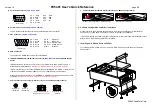
7. Installing 2.5" HDD and fixers on FX5401
The following figure will guide you how to install 2.5" HDD inside the FX5401 and how to install the
FX5401 fixers.
5
1
6
(Front View)
9
Pin 1: -DCD
Pin 6: -DSR
Pin 2: RXD
Pin 7: -RTS
Pin 3: TXD
Pin 8: -CTS
Pin 4: -DTR
Pin 9: -RI
Pin 5: Ground
1
5
(Front View)
11
15
Pin 1: Red
Pin 12:
DDC Data
Pin 2: Green
Pin 15:
DDC Clock
Pin 3: Blue
Pin 5 & 10: Digital Ground
Pin 13: Hsync
Pin 6,7,8: Analog Ground
Pin 14: Vsync
Others:
Not Used
Audio-Out
(Left Side)
Audio-In
(Right Side)
1
2
5
JP3
Select Microphone for
Audio-In
(Factory Preset)
6
1
2
5
JP3
Select Line-In for
Audio-In
6


