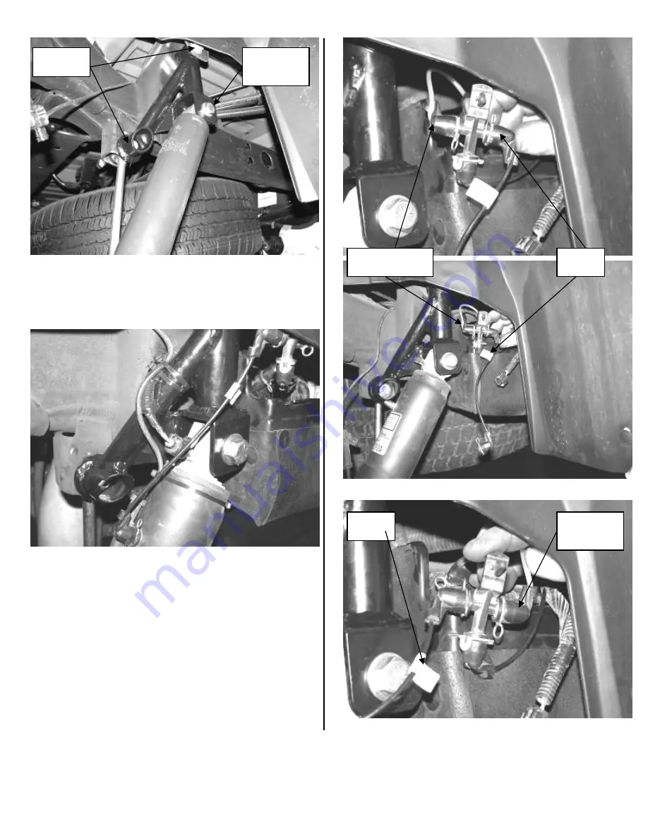
16.
Working from the driver’s side, electrical plug. Follow the
electrical plug to the plastic loom, carefully open the loom
and ONLY remove the ABS wires from it back
approximately 10 inches. Route the plug and line down to
the shock and plug in. SEE PHOTO BELOW
17.
Remove the air line manifold from its connection point in
the rear wheel well. Bring the manifold forward just behind
the rear shock. The supply line needs to be swapped on the
manifold with the line to the driver side shock. Remove the
clips from the ends and swap the two lines. Use a drill with
a 15/64” drill bit and drill a hole into the plastic liner and
insert the manifold into it. Use two of the supplied 8” zip
ties and attach the ABS & Electrical lines to the shock
extension. Use two of the supplied 14” zip ties and attach
the ABS line to the shock ABOVE THE SHOCK
BLADDER. SEE PHOTOS
Photos above show factory routing of air lines into manifold
Factory
hardware
Supplied
9/16” x 3”
Hardware
Supply line from
compressor
Line to
shock
Line to
shock
Supply line
from
compressor


