background image


16.


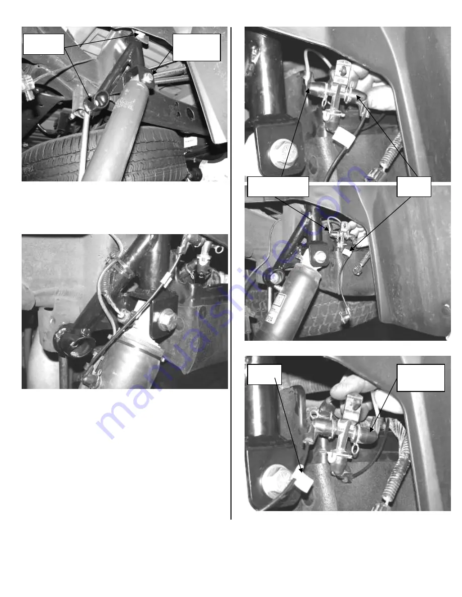
Working from the driver’s side, electrical plug. Follow the 
electrical plug to the plastic loom, carefully open the loom 
and ONLY remove the ABS wires from it back 
approximately 10 inches. Route the plug and line down to 
the shock and plug in. SEE PHOTO BELOW 


17.


Remove the air line manifold from its connection point in 
the rear wheel well. Bring the manifold forward just behind 
the rear shock. The supply line needs to be swapped on the 
manifold with the line to the driver side shock. Remove the 
clips from the ends and swap the two lines. Use a drill with 
a 15/64” drill bit and drill a hole into the plastic liner and 
insert the manifold into it. Use two of the supplied 8” zip 
ties and attach the ABS & Electrical lines to the shock 
extension. Use two of the supplied 14” zip ties and attach 
the ABS line to the shock ABOVE THE SHOCK 
BLADDER. SEE PHOTOS 


Photos above show factory routing of air lines into manifold 


Factory 

hardware 

Supplied  

9/16” x 3” 

Hardware

Supply line from 

compressor 

Line to 

shock 

Line to 

shock 

Supply line 

from 

compressor

Summary of Contents for FTS21052BK

Page 1: ...ON CHECK ALL PARTS INCLUDED IN THIS KIT TO THE PARTS LIST ABOVE BEFORE BEGINNING INSTALLATION OF THE KIT IF ANY PIECES ARE MISSING CONTACT FABTECH AT 909 597 7800 VEHICLES THAT WILL RECEIVE OVERSIZED...

Page 2: ...Bracket Drv 1 FT20319BK Rear Bump Stop Bracket Drv 1 FT20320BK Rear Bump Stop Bracket Pass 1 FT20320BK Rear Bump Stop Bracket Pass 1 FT20349 Brake Line Bracket 1 FT20349 Brake Line Bracket 4 FT20351...

Page 3: ...ir line connections Remove the lower pivot bolt that attaches the track bar to the axle bracket and save SEE PHOTO BELOW 4 Lower the floor jack to release the coil springs Remove the coil springs from...

Page 4: ...d remove the factory upper links arms If the rear is equipped with Auto Ride locate the Auto Ride sensors on both the driver side and passenger side of the vehicle on the upper link arms Disconnect fr...

Page 5: ...he support bracket over the two new holes and install with the 7 16 x 2 bolts and hardware Insert the 9 16 x 4 bolt into the trac bar bracket and support bracket tighten just enough to make the bracke...

Page 6: ...FACTORY UPPER AND LOWER SHOCK MOUNTS 13 Repeat step twelve on the passenger side of the truck 14 Place a floor jack under the rear axle Attach your coil spring compressor onto the new rear coil sprin...

Page 7: ...be swapped on the manifold with the line to the driver side shock Remove the clips from the ends and swap the two lines Use a drill with a 15 64 drill bit and drill a hole into the plastic liner and i...

Page 8: ...Shock Above Shock Bladder 18 Repeat steps sixteen and seventeen on the passenger side there is no air line manifold on the passenger side RESUME INSTALL OF ALL KITS 19 Remove the 9 16 x 4 bolt from t...

Page 9: ...specifications can be found in your owner s manual 22 Remove the jack stands and set the truck back onto the ground Torque the Upper and Lower Link arm bolts to 100 ft lbs Check the torque on all the...

Page 10: ...ing systems air bag systems and should not be installed if the vehicle is equipped as so Fabtech makes every effort to ensure suspension product compatibility with all vehicles listed in the catalog b...

Reviews: