background image

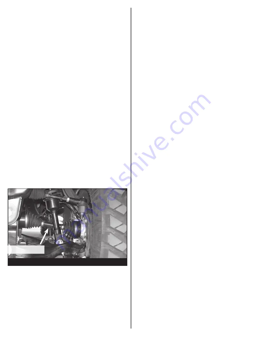
- FIGURE 65 -

NOTE: Specific IWE “Integrated Wheel End” installation 
procedures are necessary when servicing and/or IWE 
vacuum is released. When the IWE actuator is loosened at 
the knuckle and/or removed from CV shaft:

•  Remove the two vacuum line, compress the IWE actuator 

and install a vacuum cap on the larger vacuum port (to 
keep it compressed).

•  Install the IWE actuator onto the halfshaft outer end (if 

removed).

•  Do not dislodge the IWE seal spring when installing 

an IWE on a CV halfshaft outboard end or component 
damage may occur. 

•  Allow the wheel knuckle to swing outward while keeping 

the halfshaft pushed inward. 

•  Once clearance is available, install the halfshaft outboard 

end into the wheel knuckle hub bearing.

•  Connect the upper ball joint and install new nut; torque to 

85 ft-lbs.

•  Install the three IWE actuator to wheel knuckle retaining 

bolts; torque to 106 ft-lbs

•  Remove the IWE vacuum cap and reconnect the vacuum 

tubes. 

•  Verify the spline engagement by checking for spline lash 

before installing the axle nut or component damage may 
occur. 

•  Install new axle nut; 30 ft-lbs

Procedure for checking proper 

installation of HUB actuator.

•  The IWE system uses vacuum hubs that engage the front 

wheel hubs to the front halfshafts or disengage the front 
wheel hubs from the front halfshafts. 

•  The IWE solenoid receives engine vacuum from the 

vacuum reservoir.

•   When the 4-wheel drive system is in 2WD mode, the 4x4 

module (PCM) supplies a ground path to the IWE solenoid 
to apply vacuum to the wheel ends (disengaging the front 
hubs from the front halfshafts). In 4WD mode, the 4x4 
module (PCM) does not supply the ground path to the 
IWE solenoid, vacuum is not applied to the integrated 
wheel ends and an internal spring keeps the front hubs 
engaged to the front halfshafts.

1.  With the vehicle on level ground. Engage the emergency 

brake and chalk the rear wheels. 

2.  Jack up the front driver side enough so the wheel/tire 

spins freely. 

3.  With the vehicle in PARK, start the engine. 

NOTE: MAKE 

SURE THE VEHICLE IS PLACED IN 2WD.

 Rotate the 

wheel/tire and check to see if the CV halfshaft rotates. If 
the CV halfshaft rotates, either a vacuum leak is present or 
the IWE (Intergrated Wheel End) was installed improperly. 


NOTE: DO NOT OPERATE THE VEHICLE OR DAMAGE 
WILL OCCUR. SEE FIGURE 56 

4.  If the CV halfshaft remains stationary when the wheel/tire 

is rotated repeat steps 1-3 on the front passenger wheel/
tire.

CV HALFSHAFT

Summary of Contents for FTS22179

Page 1: ...s 4331 Eucalyptus Ave Chino CA 91710 Tech Line 909 597 7800 Fax 909 597 7185 Web www fabtechmotorsports com INSTALLATION INSTRUCTIONS 2015 18 FORD F150 4WD FTS22179 6 BASIC SYSTEM FTS22181 6 PERFORMAN...

Page 2: ...AS16 DRIVER WARNING DECAL 1 FTREGCARD REGISTRATION CARD FT30603 HARDWARE KIT LOCATION 6 5 16 SAE WASHER G5 ZINC BRAKE LINE 3 5 16 18 STOVER NUT G5 Z1 3 5 16 18 X 1 HEX BOLT G8 ZINC 8 7 16 SAE WASHER G...

Page 3: ...nter of gravity of the vehicle and may increase roll over as compared to stock On EcoBoost 3 5L and 2 7L models discard all air shields OEM Wheels and tires cannot be used after the installation of th...

Page 4: ...t the tie rod ends from the steering knuckle by striking the knuckle to dislodge the tie rod end SEE FIGURE 2 6 Remove factory Tie Rod end and discard SEE FIGURE 3 FIGURE 3 STEP 6 FIGURE 2 STEP 5 7 Re...

Page 5: ...rs and save for re installation SEE FIGURES 8 9 11 Locate the three upper coilover nuts and remove Save the hardware Remove the shock assembly from the vehicle and mark Driver for assembly to install...

Page 6: ...s the rear of the vehicle You will need to cut and sand a radius in the rear side of the pocket in order to clear the differential housing SEE FIGURE 17 14 Remove the front drive shaft bolts where the...

Page 7: ...Fabtech upper differential mounts using two 13 x 4 hex cap bolts washers and lock nuts Leave all hardware loose in preparation of the installation of the remaining differential mounts SEE FIGURE 20 2...

Page 8: ...24 23 On the front axle tube remove the rear and lower bolts to allow for the new center differential bracket to be mounted 24 Mount the differential bracket to the center of the differential using th...

Page 9: ...factory front control arm pockets using the factory hardware Make sure the skid plate tab on the crossmember is facing the Fabtech rear crossmember Leave the hardware loose at this time SEE FIGURE 31...

Page 10: ...and FT30605BK Pass shock spacers 35 Locate the factory coilovers Using a press press the factory studs out of the bar pins SEE FIGURE 34 36 Install the Driver side spacer on the driver side coilover u...

Page 11: ...30600D and install the factory hub Torque the four 14mm bolts to 160 ft lbs SEE FIGURE 40 41 Re install the 4WD actuator using the 3 factory bolts Torque to 29 ft lbs SEE FIGURE 41 42 Install the Fabt...

Page 12: ...Fabtech bracket Using the factory hardware mount factory brake line bracket to the side of the Fabtech knuckle After installing the factory brake line bracket check to insure full movement by steerin...

Page 13: ...hardware install the factory sway bar to the frame using the FT30591 driver side bracket and the FT30590 passenger side bracket When mounting the sway bar will be offset towards the rear of the truck...

Page 14: ...nd FTS6266 shocks are to be installed with the body down 56 Install tires and wheels and torque lug nuts to wheel manufacturer s specifications Turn front tires left to right and check for appropriate...

Page 15: ...roper installation of HUB actuator The IWE system uses vacuum hubs that engage the front wheel hubs to the front halfshafts or disengage the front wheel hubs from the front halfshafts The IWE solenoid...

Page 16: ...el sizes listed in Fabtech s website are only a guideline for street driving with noted fender trimming Fabtech is not responsible for damages to the vehicle s body or tires Fabtech is not responsible...

Reviews: