27
AC/DC Voltage Measurement:
1. Rotate function selection switch to voltage
measurement position.
2. Press “
FUNC
” key to select AC or DC voltage.
3.
Connect the black test probe to the
COM
input jack and
the red probe to the
V
input jack.
4. Read the measured value from LCD display. When
measuring DC voltage, the display will simultaneously
show the voltage polarity which is connected with red
test probe.
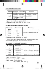
Resistance and Continuity measurement:
WARNING
When measuring resistance or circuit continuity, to
avoid injury or meter damage, turn off the power to
the circuit and discharge all capacitors.
1. Rotate function selection switch to resistance
measurement position, and turn off the power to
the circuit to be tested.
2.
Connect the black test probe to the
COM
input jack and
the red probe to the
V
input jack.
3. Measure the resistance of circuit to be tested with
other ends of test probes.
4. Read the resistance value from LCD display. If it
is overload, “
OL
” will display on the LCD display.
5. If the measured circuit resistance is less than about
40Ω, the buzzer will sound continuously.
Here are some tips for measuring resistance:
•
The resistance measured on a circuit is usually
different from the rated value of resistance. This is
because the test current of the meter will flow through
all possible channels between test probes.
NU-711B_0618 7 langues.indd 27
22/06/2018 09:20:54

