background image

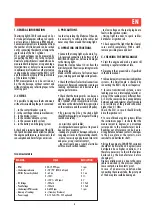
1. GENERAL INFORMATION

The timing light X.730 B can be used on 2 or 

4 stroke petrol engines with up to 2 sparks 

per revolution. Stroboscopic RPM and ad-

vance measurements are independent from 

the number of cylinders and can be carried 

out by connecting the inductive clamp to the 

spark cable of the No.1 cylinder.

DC or peak voltages can be measured by 

connecting the RED 1 clip to the test point. 

Dwell of each distributors’ camshafts can be 

measured both in degrees or in percentage.

Injection time or duty cycle measurements 

in milliseconds of injectors or other actuators 

can be made by connecting the RED 1 CLIP 

and the inductive clamp to the spark cable 

of the relevant cylinder.

RPM measurements can be carried out 

by the stroboscope, without contact and 

without sticking any refl ecting tapes to the 

rotating part.

2. CHECKS

It is possible to diagnose faults and wears 

without disassembling the part concerned:

1 - in the contact breaker system;

2- in the centrifugal advance mechanism;

3 - in the timing system;

4 - in the vacuum advance system;

5 - in the vacuum retard system;

6 - in the battery and charging system.

A check and a correct adjusting of the diffe-

rent parts described above allow to optimize 

the engine performance, reduce wears, fuel 

consumption and harmful gas emissions.

3. PRECAUTIONS

In order to prolong the lifetime of the unit, 

it is necessary to softly coil the cables but 

never wrap them around the timing light.

4. OPERATING INSTRUCTIONS

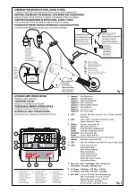
• Connect the timing light as shown in Fig. 

1.A reversed connection to battery of the 

RED/BLACK clips does not cause damages 

to the timing light.

Mount the clamp at about 10 cm from the 

distributor, with the arrow pointing towards 

the spark plug.

Make sure the cables are far from exhaust 

pipes, rotating parts and high voltage leads.

• Check that the coil’s electrical connections 

are correct. Reversed connections can cause 

reading unsteadiness and decrease the 

engine performance.

• Check that the timing marks can be seen 

clearly; bring otherwise the piston of the 

No.1 cylinder at TDC in compression stroke, 

and trace with a white chalk two signs in line 

on the crankcase and the crankshaft pulley.

• By pressing the D key, the strobe light 

should fl ash regularly; an irregular fl ashing 

could be caused by :

- non-resistive spark cables;

- discharges between cap poles or to ground 

due to dirt or moisture;

- leakage to ground or between cables due 

to ageing or cracks in the insulating sheath;

- wear or excessive gap between rotor arm 

and poles or cap’s central contact;

- too small spark gap or spark electrodes 

with too much carbon residues;

- too low voltage on the spark plug due to 

faults in the ignition system;

- timing light too near to spark cables, 

distributor or ignition coil.

• Check against the light that the clamp’s 

cores match completely. With a cloth, 

remove possible grease and dust.

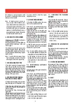
5. CHECKING THE DWELL ANGLE

• Start the engine and make it warm till 

reaching a regular rotation at idle.

• Disconnect the vacuum tube, if specifi ed 

in the data manual.

• In breaker points or transistorized ignition 

systems, the Dwell angle is checked by 

connecting the RED 1 clip to coil negative.

• In some transistorized systems, a zero 

reading means an interrupted reluctor or 

wiring. If the reading is very different from 

3÷5 ms, the causes can be: a wrong distance 

between poles and reluctor, a faulty module 

or a resistance of the ground connection 

higher than 0.1 Ohm.

Check the ECU, in case it should directly 

drive the ignition coil.

• In case of breaker points systems follow 

the instructions page 7 to check that the 

measurement in degrees or percentage 

corresponds to the manufacturer’s data. 

Readings out of tolerance can be due to: 

wrong distance between contacts, damages 

to the base plate or the contacts, worn 

camshaft and distributor shaft .

• Bring the engine to 2000 RPM, variation 

should not be more than 3 degrees (some 

distributors have higher variations, it is 

therefore necessary to check the features 

declared by the manufacturer before 

changing it).

Higher variations can be due to the same 

causes described in the previous chapter, 

loose contacts, used contacts’ pivot.

In case of an excessive variation when 

connecting the vacuum tube, the pivot post 

of the base plate could be damaged.

TECHNICAL FEATURES

READING    


SCALE 

RESOLUTION

– RPM  

400÷19.999 rpm  

1 rpm

– Stroboscopic advance  

0÷78°/90° (400/465 rpm)  

0.1°

– DWELL (for each cylinder)  

0÷ 65 ms  

0.1 ms

 0÷100% 

 0.1%


0÷120° (> 600 rpm)  

0.1°

– DC Voltage  

1÷70 Volts  

0.1 Volt

– Peak Voltage  

1÷70 Volts  

0.1 Volt

– Stroboscopic RPM counter  

60÷6000 rpm  

1 rpm

– Memory of readings  

6 s (from key D release)

– Power supply  

9.5÷15 Volts (9.5÷35 V optional)

EN

5

Summary of Contents for X.730B

Page 1: ...wijzing Guia de instrucciones Istruzioni per l utilizzo Instrukcja obs ugi Manual de instru es NU X 730B 0102 X 730B Lampe Stroboscopique Timing Light Stroboskoplicht Stroboscooplamp L mpara Estrobosc...

Page 2: ...Notes...

Page 3: ...min V Volt Dwell 1...

Page 4: ...tMort Haut en phase de compression En pressant la touche D la lampe doit clignoter r guli rement des instabilit s du clignotement pourraient tre caus es par c bles bougie non r sistifs d charges entre...

Page 5: ...teur Note Pourcertainsv hicules lesrep resde r f rence peuvent tre mieux illumin s en tenant la lampe stroboscopique en position inconfortable pour la lecture En ce cas rel cher la touche D quand les...

Page 6: ...nombre de cylindres Appuyer une fois sur la touche pour confirmer L appareil sera pr t pour la mesure S LECTION DU NOMBRE D TINCELLES PAR TOUR L appareil est programm pour une tincelletouslesdeux tour...

Page 7: ...egularflashing could be caused by non resistive spark cables dischargesbetweencappolesortoground due to dirt or moisture leakage to ground or between cables due to ageing or cracks in the insulating s...

Page 8: ...ensorisnotfaulty If the TDC mark swings too much check the distribution belt and the distributor mechanisms in point systems Note In some vehicles reference marks can be better lightened by keeping th...

Page 9: ...the number of cylinders through key Press once key to confirm The strobotester is now ready for measurements SELECTION OF NUMBER OF SPARKS PER REV The unit is set for one spark per two revs 4 stroke e...

Page 10: ...anbringen Beim Dr cken auf Taste D muss das Stroboskop regelm ig blinken ein ungleichm iges Blinken k nnte zur ckzuf hren sein auf nicht resistive Kerzenkabel auf Schmutz oder Feuchtigkeit zur ckzuf h...

Page 11: ...gen besserbeleuchtetwerden indemmandas Stroboskoplicht in einer f r die Ablesung unbequemen Position h lt In diesem Fall TasteDloslassen wenndieMarkierungen ausgerichtet sind den Wert dann in 6 Sekund...

Page 12: ...l Zylinder auszuw hlen Einmal auf Taste dr cken um zu best tigen Das Ger t ist nun f r die Messungen bereit AUSWAHL DER ANZAHL FUNKEN PRO UMDREHUNG Das Ger t ist f r einen Funken alle zwei Umdrehungen...

Page 13: ...carter et sur la poulie de l arbre moteur avec le piston du cylin re No 1 op het Bovenste Dode Punt tijdens de compressiefase Wanneer u op de toets D drukt moet de lamp regelmatig knipperen onregelmat...

Page 14: ...rt u de temperatuursensor van de motor N B In sommige voertuigen kunnen de referentiemerkstrepen beter verlicht worden door de stroboscooplamp in een ongerieflijke afleespositie te plaatsen Laat in di...

Page 15: ...ntal cilinders te selecteren Druk n keer op toets om te bevestigen Het apparaat is klaar voor de meting SELECTIE VAN HET AANTAL VONKEN PER TOER Het apparaat is geprogrammeerd voor n vonk iedere twee t...

Page 16: ...o humedad dispersiones hacia la masa o entre los cables debido al envejecimiento del aislamiento o a fisuras existentes en el mismo desgaste y distancia excesiva entre el dedo del distribuidor de enc...

Page 17: ...iones indicado en los datos ConlateclaC lleveelindicadoraln mero de grados se alado en los datos las marcas de PMH del c rter y de la polea del rbol motor deber n coincidir Si el error es excesivo com...

Page 18: ...o de cilindros Pulse una vez la tecla para confirmar El aparato estar listo para la medici n SELECCI N DEL N MERO DE DESTELLOS POR REVOLUCI N Elaparatoest programado para efectuar un destello cada dos...

Page 19: ...verso massa o fra i cavi dovuta ad invecchiamento o crepe nell isolante usura ed eccessiva distanza fra spazzola rotante e poli o contatto centrale della calotta elettrodi della candela troppo vicini...

Page 20: ...ni di distribuzione Nota In alcuni autoveicoli le tacche di riferimento possono essere illuminate meglio tenendo la pistola in posizione scomoda per la lettura Per memorizzare la lettura rilasciare il...

Page 21: ...2 Selezionare il numero di cilindri tramite il tasto Premere il tasto una volta per confermare Lo strumento sar pronto per la misura SELEZIONE DEL NUMERO DI SCINTILLE PER GIRO Lo strumento impostato p...

Page 22: ...zy po czenia elektryczne cewki s prawid owe Odwrotne po czenie mo e spowodowa nieregularne odczyty i zmniejszenie wydajno ci silnika Sprawdzi czy punkty odniesienia s widoczne w przeciwnym razie nale...

Page 23: ...odniesienia mog by lepiej pod wietlone gdy lampa stroboskopowa znajduje si w po o eniu niewygodnym dla odczytu W tym przypadku zwolni przycisk D kiedy punkty odniesienia s wyr wnane i w ci gu 6 sekun...

Page 24: ...nia cewki kontrolowanegocylindra Wprzypadkusilnik wzliczb cylindr winn ni 4 ponaci ni ciuprzycisku po raz pierwszy pojawi si wy wietlenie podane na rysunku 2 Nacisn przycisk aby wybra liczb cylindr w...

Page 25: ...teclaD al mpadadeveapresentar uma intermit ncia regular a intermit ncia irregular pode ser causada por cabos vela n o resistivos descargas entre os p los da cabe a do distribuidor ou para a terra devi...

Page 26: ...otor Nota para determinados ve culos as marcas de refer ncia podem receber uma ilumina o melhor mantendo a l mpada estrobosc pica numaposi opoucoconfort velparaaleitura Neste caso soltar a tecla D qua...

Page 27: ...vez a tecla para confirmar O aparelho fica pronto para proceder medi o SELEC O DO N MERO DE FA SCAS POR ROTA O O aparelho est programado para uma fa sca a cada duas rota es motores a 4 tempos com dist...

Page 28: ...21 13 Fax 91 778 27 53 ITALIA SWK Utensilerie S r l Sede Operativa Via Volta 3 21020 Monvalle VA ITALIA 0332 790326 Fax 0332 790307 POLSKA STANLEY Black Decker Polska Sp zo o ul Post pu 21D 02 676 Wa...

Reviews: