background image

 3.3 FCU Fit

An outline (plan view) drawing of the FCU circuit board is shown in Figure 3.3.1. Note that 

if the diagram is printed on A4 paper it is to scale.

Crucially, the FCU board has dimensions of 23.2 cm x 14.5 cm x 2.5cm (width x length x 

height) and would usually be placed in the fader tray directly underneath the faders which 

it controls.  

10

Summary of Contents for Master Control Unit

Page 1: ...Product Fitting Guide v1 0 0 October 2018 2018 FaderMate All rights reserved 1...

Page 2: ...bles 9 3 3 FCU Fit 10 3 4 Cabling 14 3 5 Planning Your Installation 16 4 Fitting Instructions 18 4 1 Before You Begin 18 4 2 Setting FCU IDs 18 4 3 Installing FCUs and Routing Daisychain Cables 20 4 4...

Page 3: ...ust be installed in the fader tray void The FaderMate system as a whole is controlled by a 1U rackmount Master Control Unit MCU see section 2 2 1 2 Document Outline This document explains the followin...

Page 4: ...s A FaderMate system comprises two subsystem kits a single Master Control Unit MCU kit and up to 4 Fader Control Unit FCU kits 2 2 MCU Overview The Master Control Unit is the heart of the FaderMate sy...

Page 5: ...ength of two core power cable e 1 x IEC mains cable f 1 x USB type A to type B configuration cable A full MCU kit is shown in Figure 2 3 1 Figure 2 3 1 MCU Kit Contents 2 4 FCU Overview The Fader Cont...

Page 6: ...FCU kit contains the following components 1 x FaderMate FCU module 8 x Alps motorised faders fitted with custom ribbon cables 8 x metallised fader knobs A full FCU kit is shown in Figure 2 5 1 Figure...

Page 7: ...Channel Installation Block Diagram A single MCU can support between 1 and 4 inclusive FCUs and thus up to 32 moving faders can be accommodated There is no reason in principle that an installation coul...

Page 8: ...ere must be a way to get the necessary data interface and power cables inside the console and connected to one of the FCU circuit boards It may also be useful to refer to sections 2 System Overview an...

Page 9: ...1 2 Typical Motorised Fader Space Constraints 3 2 Fader Cables The faders supplied as part of the standard FCU kit are fitted with cables 10cm in length If required to accommodate mechanical peculiar...

Page 10: ...wn in Figure 3 3 1 Note that if the diagram is printed on A4 paper it is to scale Crucially the FCU board has dimensions of 23 2 cm x 14 5 cm x 2 5cm width x length x height and would usually be place...

Page 11: ...Figure 3 3 1 FCU Circuit Board Dimensions 11...

Page 12: ...systems which include more than 1 FCU Figure 3 3 2 FCU Boards With FaderMate System Connections The standard motorised fader including connector adds a further 3 5cm to the required fader tray depth g...

Page 13: ...rd and Motorised Fader Installed in Console Figure 3 3 4 illustrates the total FCU system component stack up which determines the required fader tray depth Figure 3 3 4 FCU Circuit Board and Motorised...

Page 14: ...way ribbon cable of length 2 metres terminated at both ends by DB25 connectors Power cable a 2 core cable of length 2 metres and diameter 6mm Figure 3 4 1 shows the master data interface cable Figure...

Page 15: ...the console are Cutting drilling panels and grommeting the hole s Feeding the cables through existing gaps in the metalwork Note that the data interface cable is 2 metres long It is therefore not poss...

Page 16: ...each other Some designs split the console into sections Sometimes the sections buckets don t contain multiples of 8 faders and so faders controlled by a single FCU may be some distance from the board...

Page 17: ...ing drilling or other physical modifications to your console NOTE If in doubt please arrange to have the work completed by a suitably knowledgeable technician We have a small network of approved insta...

Page 18: ...ay be damaged by Electrostatic Discharge ESD Proper handling precautions must be observed If in doubt please seek the help of an appropriately qualified technician before proceeding 4 2 Setting FCU ID...

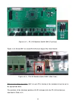
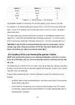
Page 19: ...dge of the circuit board Figure 4 2 2 FCU ID Selection Switch SW1 Rear View Prior to connecting any cables SW1 on each FCU module in the installation must be set to the appropriate state The positions...

Page 20: ...t all FCU IDs have been double checked before connecting any cables or powering up the MCU 4 3 Installing FCUs and Routing Daisychain Cables NOTE Only perform this step if you are actually installing...

Page 21: ...Data Interface Figure 4 4 1 shows the location of the data connector on the rear panel of the MCU Figure 4 4 1 MCU Data Connector Figure 4 4 2 shows the location of CON1 the master data connector on...

Page 22: ...nt which particular FCU module is connected to the MCU and the choice should be determined by mechanical convenience considerations All of the FCUs in the installation must have their HDR1 connectors...

Page 23: ...Figure 4 4 4 Data Connections 23...

Page 24: ...CU rear panel Figure 4 5 1 MCU Power Terminals Figure 4 5 2 shows the location of the power terminals CON2 and CON3 on the FCU circuit board Figure 4 5 2 FCU CON2 and CON3 Power Terminals TIP You are...

Page 25: ...o the terminal of CON2 on the same FCU using the brown wire in the two core pair The wires should enter the rear of the FCU power connector Figure 4 5 3 shows connections at both ends of the MCU FCU p...

Page 26: ...Figure 4 5 4 Daisychain Power Connections Block Diagram 26...

Page 27: ...power supply wires connected incorrectly may cause serious damage Connect the MCU to the mains using the supplied IEC cable Turn the MCU power on using the front panel rocker switch You should observe...

Page 28: ...om the mains before continuing 4 7 Removing the Old Faders NOTE Only perform this step if you are actually installing the system in a console If you are performing a dry run to ensure that the system...

Page 29: ...Plate With the fader detached from the console metalwork it is now necessary to disconnect it electrically from the console WARNING Before modifying any of the console s internal wiring ensure that t...

Page 30: ...es it is important to leave as much slack as possible i e to cut the wire very close to the soldered terminal on the fader otherwise the wire may not reach the motorised fader It is important to remem...

Page 31: ...elevant FCU by means of the connectors labelled AFn where n can be any number between 1 and 8 inclusive Figure 4 8 1 illustrates the positions of these connectors on the FCU board Figure 4 8 1 FCU Aud...

Page 32: ...om ribbon cable as supplied in the FCU kit Figure 4 9 1 FaderMate Standard Motorised Fader First screw each motorised fader to the appropriate faceplate using the mounting screws that have been remove...

Page 33: ...in case you need to disassemble the system to check the connections after doing a basic system test It is extremely important to check that there is no risk of stray pieces of conducting material e g...

Page 34: ...ld see is the Wave startup routine which causes the faders to move in the shape of a sine wave for around 3 seconds as the system is started up If you would like to perform a more extensive movement t...

Page 35: ...sensing does not operate correctly It is not possible to cause the DAW fader to go to inf or full scale The motorised faders never reach the extremes of their travel Calibration is performed using the...

Page 36: ...Version History Version Date Author Details 1 0 0 08 October 2018 AJN First release 36...

Reviews: