background image

  4

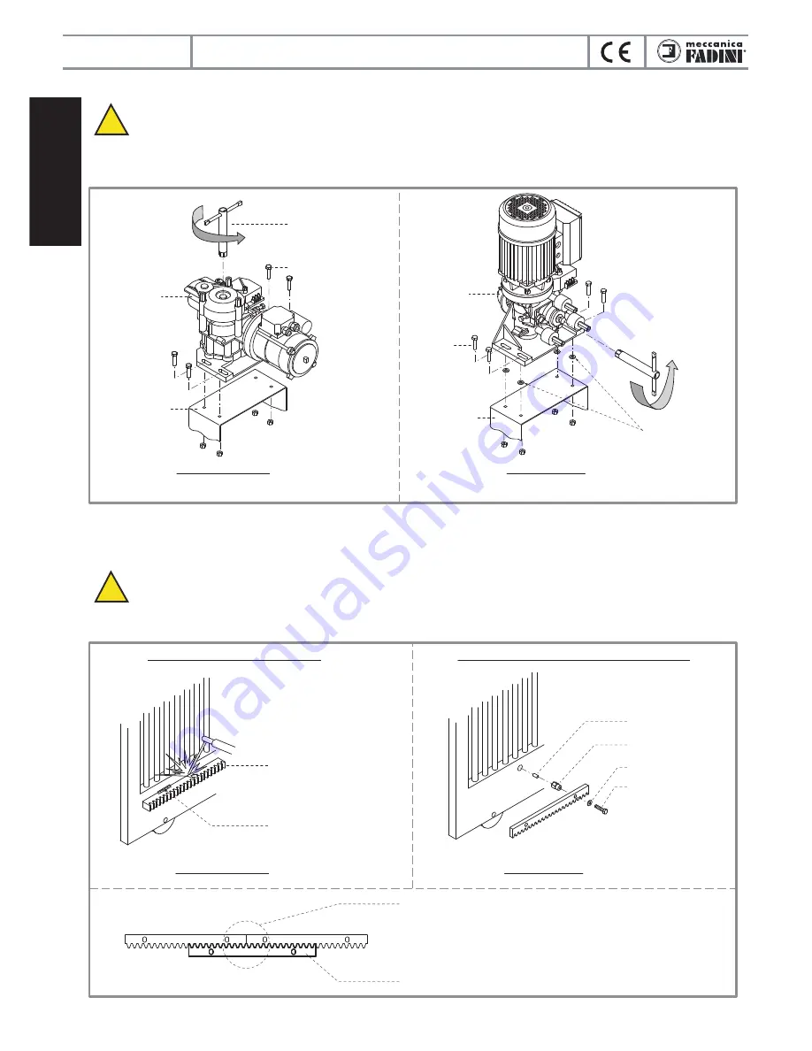
RACK FITTING OPERATIONS
 IMPORTANT:

 if installing Mec 200 vertical it is recommended to insert 2 mm shims between the fixing bracket and


the operator base plate before welding the rack to the gate, so that rack and gear mesh each other with an adequate


clearance after that the shims have been removed.

Temporary fix Mec 200 on to the fixing bracket, perfectly levelled, by means of the 4 fixing screws. Mec 200 outer gear must run 

idle: loosen (by 1 or 2 turns max.) the hexagonal head screw by means of the release spanner E 17 supplied with the equipment

(pic. 3).

While fixing the rack it is required that the Mec 200 driving gear is not connected with the gate and it can be made run idle by means

of the release spanner E17 supplied with the equipment; the gate can be freely moved by hand.

Temporary clamp the rack to the gate so that it can adequately mesh the driving gear: the rack must mesh the driving gear, idle, of 

Mec 200 in a very smooth way, without friction (pic. 4).

 IMPORTANT:

 before definitely fixing any component, make sure that the rack can mesh the driving gear of Mec 200


so that the whole system, gate included, can be smoothly run by hand the full travel open and close without any


friction.

Remove the 2 mm shims only after having fixed the rack. An adequete clearance between rack and gear has thus been achieved 

(pic. 4).

English

Pic. 3

Pic. 4

MEC 200

MEC 200 HORIZONTAL

MEC 200 VERTICAL

MEC 200 HORIZONTAL

MEC 200 VERTICAL

RACK FIXING BY WELDING IT TO THE GATE

RACK FIXING BY MEANS OF SCREWS AND FITTING PARTS

ANTI-CLOCKWISE

TO RELEASE

RELEASE SPANNER

E 17.

ANTI-CLOCKWISE

TO RELEASE

DRIVING GEAR

OR SPROCKET

RELEASE SPANNER E 17

M8 FIXING SCREWS

DRIVING GEAR

OR SPROCKET

M8 FIXING

SCREWS

FIXING BRACKET

FIXING BRACKET

22x22 mm RACK, 2 m LENGTH

THREADED PIN

DISTANCE NUT

WASHER

M8 SCREW

RIGID SPOT WELDING

PITCH GAUGING SPARE RACK

IMPORTANT:

  respect  the  same  rack  pitch  when 

joining the rack bars. Use a spare rack bar as in the 

picture to make sure that the junction has the same 

configuration.

2 mm SHIMS TO 

REMOVE AFTER 

HAVING FIXED THE 

RACK TO THE GATE

!

!

electro-mechanical sliding gate operator

Summary of Contents for MEC 200

Page 1: ... 12445 Electro mechanical sliding gate operator Vertical and horizontal installation Gear movements and worm gear coupling in oil bath fully mounted on ball bearings MEC 200 GB Instructions manual pages 1 8 the gate opener ...

Page 2: ...on The installer must inform and instruct the end user about the proper use of the system by releasing him a technical dossier including layout and components of the installation risk analysis verification of safety accessories verification of impact forces and reporting of residual risks INFORMATION FOR END USERS The end user is required to read carefully and to receive information concerning onl...

Page 3: ... gate stops are fixed in the open and closed gate positions so that the gate does not over travel the permitted limit and go out of the upper guide make sure that a system be mounted to the gate to prevent it from falling over make sure that once at the end of the permitted travel the gate does not hit the gate posts or special gate stops to avoid damages to its structure FITTING MEC 200 ON TO THE...

Page 4: ...out friction pic 4 IMPORTANT before definitely fixing any component make sure that the rack can mesh the driving gear of Mec 200 so that the whole system gate included can be smoothly run by hand the full travel open and close without any friction Remove the 2 mm shims only after having fixed the rack An adequete clearance between rack and gear has thus been achieved pic 4 English Pic 3 Pic 4 MEC ...

Page 5: ...s the installer s responsibility to lay the connection pipes and tubes as properly and correctly required IMPORTANT all the electrical equipment to be properly earthed English MEC 200 Pic 5 Pic 6 15 mm LIMIT SWITCH STRIKING PLATE TO BE FIXED TO THE GATE BY BOLTS LIMIT SWITCH ROLLER FADINI 1 2 9 8 3 11 4 5 17 6 7 10 12 13 13 14 15 16 230 V n 2x1 n 2x1 n 4x1 n 4x1 cable RG58 n 4x1 5 n 4x1 5 n 4x1 n ...

Page 6: ...be adjusted to the gate weight Adjusting is by a screw which is located on one side of the operator A special spanner E17 is provided with the equipment for this purpose unscrew the locknut the more you tighten the screw clockwise the more you increase the operator torque by unscrewing it torque is decreased Once set it to meet the site requirements tighten the locknut hard pic 9 ELECTRIC MOTOR CO...

Page 7: ...el Dimensions per gate leaf Weight per gate leaf Installation date Quantity of models installed Maintainer Date NOTE WELL this document must record any ordinary and extraordinary services including installation maintenance repairs and replacements to be made only by using Fadini original spare parts This document for the data included in it must be made available to authorized inspectors officers an...

Page 8: ...e phase 40 Nm 1 200 kg 19 5 kg 19 kg Three phase 40 Nm 1 250 kg 18 5 kg 18 kg Single phase 80 Nm 1 32 10 m 1 25 C 80 C Oil Fadini Item 706L 1 800 kg 23 5 kg 23 kg IP 55 inside the cover mechanical Three phase 80 Nm 1 850 kg 21 5 kg 21 kg Three phase 110 Nm 2 000 kg 25 5 kg 25 kg Mec 200 vertical Mec 200 horizontal OVERALL DIMENSIONS FITTING ACCESSORIES FOR INSTALLING Zinc coated steel base plate 2...

Reviews: