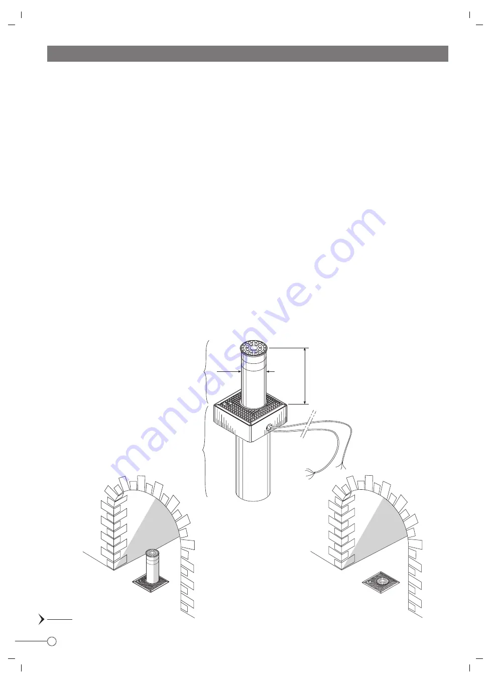
background image

2

Ø 200

PIC. 1

INSTRUCTIONS TO FOLLOW FOR THE INSTALLATION OF THE AUTOMATION VIGILO 2250

IGILO


2250

V

FOR A PERFECT APPLICATION AND CORRECT PERFORMANCE OF THE EQUIPMENT IT IS RECOMMENDED TO FOLLOW THESE
INSTRUCTIONS AND DIAGRAMS
IMPORTANT: THE INSTALLATION IS TO BE CARRIED OUT BY A QUALIFIED TECHNICIAN IN COMPLIANCE WITH THE SAFETY NORMS
EN 12453 - EN 12445, AND THE MACHINE DIRECTIVE 98/37/CE.  A COMPLETE RISK ANALYSIS IS TO BE MADE IN COMPLIANCE WITH
THE EXISTING SAFETY REGULATIONS

GENERAL FEATURES

This product can be classified as a type of automated bollard, fully retractable into the ground. It is easy and simple to install as no
special adjusting or calibration is required. The main application is traffic control. VIGILO 2250 is an electro-hydraulically operated post
having a Ø 200 mm diametre and a max. stroke of 500 mm.
The main advantage of this product is semplicity of installation: soon after fixing the location enclosure, fit the mechanism into it, carry
out the electrical connections and the system is ready to work.
Once a pulse is given (either by keyswitch or remote control), the post starts rising. A reflecting sticker makes it well visible, and an
optional flashing lamp or traffic lights ensure clear indication of the post movements or status. An electronic control panel fitted with
a microprocessor allows full automatic operations as required (optional sensing loops, photocells etc. ...) can be connected.

PRELIMINARY LOCATION CONSIDERATIONS

Before commencing installation ensure that:
- The area where the enclosure is to be located is free from underground services, which may interfere with installation.
- The properties of the soil are adequate to the required application.
- No obstruction interferes with the post movements.

Vigilo 2250 flush
with road level
to allow access

Stroke 500 mm

Vigilo 2250 raised
above ground level
to stop traffic

The post is vertically operated to

rise above the road pavement

Enclosure assembly to be

located underground in a

suitable pit

Cable length 10 metres

Summary of Contents for VIGILO 2250

Page 1: ...FITTING INSTRUCTIONS GB ...

Page 2: ...fter fixing the location enclosure fit the mechanism into it carry out the electrical connections and the system is ready to work Once a pulse is given either by keyswitch or remote control the post starts rising A reflecting sticker makes it well visible and an optional flashing lamp or traffic lights ensure clear indication of the post movements or status An electronic control panel fitted with ...

Page 3: ...an be easily lifted out using mechanical aid Pic 2 IMPORTANT make sure the electric cables are not damaged or accidentally removed from termination ENCLOSURE COVER PLATE HYDRAULIC MOTOR PUMP POST COVER EDGE PROTECTION RUBBER RING HOUSING CYLINDER AND PISTON ASSEMBLY CABLE OF THE OPEN LIMIT SWITCH LOWERED POST 10 METRE LENGTH ELECTRIC MOTOR CABLE 10 METRE LENGTH LIFTING EYE LIFTING MECHANISM RISING...

Page 4: ...ide of the enclosure to the tube centre line Pic 13 and 14 Front view View of the side where a hole is provided for a cable duct to be fitted A hole will be required in the road surface where Vigilo 2250 is to be located as indicated in Pic 5 Provision is made within the unit for the entry of a Ø 50 mm duct to the electronic control unit the cables are 10 m long Provide a soakaway by pouring shing...

Page 5: ...ch cables should be pulled through the duct a rope pull through previously inserted and the inner assembly gently lowered onto the location enclosure IMPORTANT Pull the electric motor and limit switch cables through the duct to the control unit Be careful not to damage or remove the cables from their termination Pic 7 Once satisfied that the guide tube assembly is properly fitted inside the locati...

Page 6: ...ld be connected as indicated in the diagram a 20μF capacitor in parallel with the two live terminals Control unit ELPRO 10 PLUS CEI Power supply 230V 50Hz Electric Motor Cable 20μF capacitor fitted inside Elpro 10 PLUS CEI Earth Limit switch cable Important Bridge the Common and Limit Switch Close terminals 8 and 9 Read the description of the electronic control unit Elpro 10 PLUS CEI on page 8 Pic...

Page 7: ... square section of 1 5 mm2 for a distance not superior to 50 m For longer distances use 2 mm2 wires To connect the photo cells key or button operated switches and other accessories 1 mm2 wires can be used ESSENTIAL COMPONENTS OF THE INSTALLATION 1 Miri 4 flashing lamp with incorporated aerial 2 Prit 19 keyswitch 3 Polo 44 photo cell projector 4 Jubi 433 receiver in weather proof casing 5 Elpro 10 ...

Page 8: ...p while opening 2 ON Radio No reversing while opening 3 ON Automatic closing 4 ON Preflashing activated 5 ON Radio Step by step Stop in between 6 ON Dead Man Control Dip 4 OFF and Dip 3 OFF 7 ON No lamp on during dwell time 8 OFF No function T S R PULIN 3 26 27 28 3 DIP SWITCH ON OFF 1 4 5 6 7 8 2 3 L2 L3 L4 L5 L6 L7 L8 L9 1 7 4 10 11 12 13 19 20 2 8 5 3 9 6 STOP COMMON OPEN CLOSE 230V 25W max FLA...

Page 9: ...Automatic Mode 400V 50Hz THREE PHASE Holdonswitched Deadman control Pedestrian Opening Trimmer T3 OPERATING MODES from 3 to 30s It can be activated by any pulse eg by remote control superior to 2s 3 DIP SWITCH 3 ON Automatic Closing OFF No Automatic Semi automatic closing by pulse Automatic Semiautomatic Automatic Operation any pulse opens the gate the gate stays open as long as the Dwell time exp...

Page 10: ...US CEI GREEN RED Mains Supply 230V 50Hz IMPORTANT For security reasons failure of the red light prevents even the green light from illuminating Interface for the electrical connections of the green red traffic lights Traffic lights Red Light 230V 25 60W Green Light 230V 25 60W Limit Switch Contact Access Blocked Red Light Illuminated Bollard VIGILO 2250 Common Limit Swith Open Lowered bollard Limi...

Page 11: ...rd to lower the bollard 4 and eventually re establish normal operation by rotating the spanner clockwise to the original position 5 To re establish normal operation first turn the spanner clockwise to lock the hydraulic circuit make sure that the system is supplied with voltage and pulse for the bollard to rise Release spanner 3 One turn anti clockwise to over ride 2 Locate the spanner in the over...

Page 12: ...of an ever increasing process of improvement The CE mark certifies that the operator conforms to the essential requirements of the European Directive art 10 EEC 73 23 in relation to the manufacturer s declaration for the supplied items in compliance with the body of the regulations ISO 9000 UNI EN 29000 Automation in conformity to EN 12453 EN 12445 safety standard Bollard flush with ground level F...

Reviews: