7
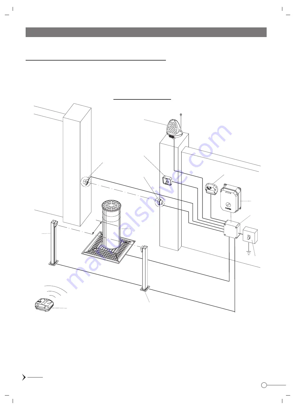
ELECTRICAL WIRING DIAGRAM
1
2
3
3
4
5
6
7
8
8
9
4 x 1 mm
2
2 x 1 mm
2
4 x 1 mm
2
4 x 1 mm
2
10
2 x 1 mm
2
cable RGB
2 x 1 mm
2
4 x 1 mm
2
2 x 1 mm
2
PIC. 9
Read the diagrams that follow carefully and familiarise yourself with their contents before starting the electrical connections (Pic. 9
and Pic. 10)
IMPORTANT: All the electrical components should be properly earthed (Pic.9).
- For
the power supply, electric motor and flashing lamp
use wires having a square section of 1,5 mm
2
for a distance not superior to
50 m. For longer distances use 2 mm
2
wires.
- To connect the
photo cells, key or button operated switches and other accessories
, 1 mm
2
wires can be used.
ESSENTIAL COMPONENTS OF THE INSTALLATION:
1 - Miri 4 flashing lamp with incorporated aerial
2 - Prit 19 keyswitch
3 - Polo 44 photo cell projector
4 - Jubi 433 receiver in weather-proof casing
5 - Elpro 10 PLUS CEI electronic control unit
6 - Electrical junction box
7 - Differential magnetic thermal mains switch
(rating 30mA , protection 6-10A)
8 - Polo 44 photo cell receiver
9 - Bollard Vigilo 2250
10 - Jubi 433 transmitter
ELECTRICAL WIRING DIAGRAM
~50 cm
Summary of Contents for VIGILO 2250
Page 1: ...FITTING INSTRUCTIONS GB ...


