background image

8

Drwg. No.

4333

In case of failure of the panel:

- Check voltage supply. It must be 230V or 400V 50Hz
- Check fuses
- Check photocells if contacts are normally closed
- Check all NC contacts
- Check that no voltage drop has occurred from the
  control panel to the electric motor

The electronic control panel Elpro 10 Plus CEI, new generation, is designed to operate sliding gates. Power supply is 230/400V
single-phase and three-phase. Built in full compliance with BT 93/68/CE Low/High Voltage and EMC 93/68/CE Electro-Magnetic
Compatibility Regulations. Fitting operations are recommended by a qualified technician in conformity to the existing safety
standards.
The manufacturing company declines any responsability for incorrect handling and application; also, it reserves the right to
change or update the control panel any time.

PLEASE NOTE:

- The control panel must be installed in a sheltered, dry place, inside the box provided with it.
- Fit the mains to the control panel with a 0.03A high performance circuit breaker.
- Use 1.5 mm

2

 section wires for voltage supply, electric motor and flashing lamp. Maximum recommended distance 50 m.

  Use 1 mm

2

 section wires for limit switches, photocells, push-buttons/key-switch and accessories.

- Bridge terminals 1 and 2 if no photocells are required.
- Bridge terminals 3 and 6 if no key- or push-button switches are required.
N.W: To fit extra accessories such as lights, CCTV etc. use only solid state relays to prevent damages to the microprocessor.
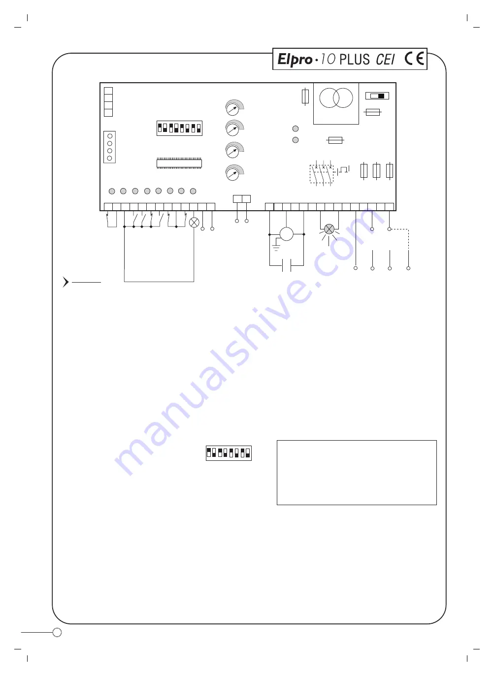
DIP-SWITCH

1

4 5 6 7 8

2

ON

OFF

3

Dip-Switch:

1= ON. Photocells. Stop while opening
2= ON. Radio. No reversing while opening
3= ON. Automatic closing
4= ON. Preflashing activated
5= ON. Radio. Step by step. Stop in between
6= ON. Dead Man Control (Dip 4=OFF and Dip 3=OFF)
7= ON. No lamp on during dwell time
8= OFF. No function

T

S

R

PULIN 3

26

27
28

3

DIP-SWITCH

ON

OFF

1

4 5 6 7 8

2 3

L2

L3

L4

L5

L6

L7

L8

L9

1

7

4

10 11 12 13

19

20

2

8

5

3

9

6

STOP

COMMON

OPEN

CLOSE

230V 25W max

FLASHING LAMP

230/400V

L1

L10

F4=630mA

Transformer

protection

F6=630mA

24V protection

RADIO
PLUG-IN
CARD CONNECTOR

TRANSFORMER

MOTOR RUN TIME
from 5 to 128s

DWELL TIME
from 5 to 128s

PEDESTRIAN
OPENING TIME
from 3 to 30s

-

+

-

+

-

+

-

+

EXT TIME (electric lock and
courtesy light) from 2 to 255s

T4

T3

T2

T1

PHOTOCELLS

SAFETY EDGE

RADIO

LIMIT SWITCH CLOSE

LIMIT SWITCH OPEN

COMMON LIMIT SWITCH

18

16

17

COMMON

M

MOTOR

U

W

V

21

22

NEUTRAL

S

LIVE

23

22

ELECTRIC LOCK OR

12V AC RELA

Y FOR

230V COUR

TESY LIGHT

RS RS

CAPACITOR

230V 50Hz

SINGLE-PHASE

VOLTAGE SUPPLY

400V 50Hz

THREE-PHASE

VOLTAGE SUPPLY

NEUTRAL

LIVE

Led Status Indication:

L1= 230V 50Hz power supply. Alight
L2= Photocells, if obstructed light goes off
L3= Open. Alight whenever an Open pulse is given
L4= Close. Alight whenever a Close pulse is given
L5= Stop. It goes off on pulsing Stop
L6= Radio. It goes on by pressing a transmitter button

L8= Limit switch Close; off when gate is closed
L9= Limit switch Open; off when gate is open
L10= It stays on for a time equal to the time set on T4

L7= Gate Status; it flashes on gate opening

24V OUTPUT max. load:

2 pairs photocells

1 radio receiver

F1=8A mains

F2=8A mains

F3=8A mains

F5=1A flashing lamp

protection

Voltage cut off switch

and cover locking knob

ELPRO 10 PLUS CEI

INDICA

TION LAMP

24V max. 3W

LIVE

LIVE

PIC. 10

ELPRO 10 plus 1.4

MICROPROCESSOR

Summary of Contents for VIGILO 2250

Page 1: ...FITTING INSTRUCTIONS GB ...

Page 2: ...fter fixing the location enclosure fit the mechanism into it carry out the electrical connections and the system is ready to work Once a pulse is given either by keyswitch or remote control the post starts rising A reflecting sticker makes it well visible and an optional flashing lamp or traffic lights ensure clear indication of the post movements or status An electronic control panel fitted with ...

Page 3: ...an be easily lifted out using mechanical aid Pic 2 IMPORTANT make sure the electric cables are not damaged or accidentally removed from termination ENCLOSURE COVER PLATE HYDRAULIC MOTOR PUMP POST COVER EDGE PROTECTION RUBBER RING HOUSING CYLINDER AND PISTON ASSEMBLY CABLE OF THE OPEN LIMIT SWITCH LOWERED POST 10 METRE LENGTH ELECTRIC MOTOR CABLE 10 METRE LENGTH LIFTING EYE LIFTING MECHANISM RISING...

Page 4: ...ide of the enclosure to the tube centre line Pic 13 and 14 Front view View of the side where a hole is provided for a cable duct to be fitted A hole will be required in the road surface where Vigilo 2250 is to be located as indicated in Pic 5 Provision is made within the unit for the entry of a Ø 50 mm duct to the electronic control unit the cables are 10 m long Provide a soakaway by pouring shing...

Page 5: ...ch cables should be pulled through the duct a rope pull through previously inserted and the inner assembly gently lowered onto the location enclosure IMPORTANT Pull the electric motor and limit switch cables through the duct to the control unit Be careful not to damage or remove the cables from their termination Pic 7 Once satisfied that the guide tube assembly is properly fitted inside the locati...

Page 6: ...ld be connected as indicated in the diagram a 20μF capacitor in parallel with the two live terminals Control unit ELPRO 10 PLUS CEI Power supply 230V 50Hz Electric Motor Cable 20μF capacitor fitted inside Elpro 10 PLUS CEI Earth Limit switch cable Important Bridge the Common and Limit Switch Close terminals 8 and 9 Read the description of the electronic control unit Elpro 10 PLUS CEI on page 8 Pic...

Page 7: ... square section of 1 5 mm2 for a distance not superior to 50 m For longer distances use 2 mm2 wires To connect the photo cells key or button operated switches and other accessories 1 mm2 wires can be used ESSENTIAL COMPONENTS OF THE INSTALLATION 1 Miri 4 flashing lamp with incorporated aerial 2 Prit 19 keyswitch 3 Polo 44 photo cell projector 4 Jubi 433 receiver in weather proof casing 5 Elpro 10 ...

Page 8: ...p while opening 2 ON Radio No reversing while opening 3 ON Automatic closing 4 ON Preflashing activated 5 ON Radio Step by step Stop in between 6 ON Dead Man Control Dip 4 OFF and Dip 3 OFF 7 ON No lamp on during dwell time 8 OFF No function T S R PULIN 3 26 27 28 3 DIP SWITCH ON OFF 1 4 5 6 7 8 2 3 L2 L3 L4 L5 L6 L7 L8 L9 1 7 4 10 11 12 13 19 20 2 8 5 3 9 6 STOP COMMON OPEN CLOSE 230V 25W max FLA...

Page 9: ...Automatic Mode 400V 50Hz THREE PHASE Holdonswitched Deadman control Pedestrian Opening Trimmer T3 OPERATING MODES from 3 to 30s It can be activated by any pulse eg by remote control superior to 2s 3 DIP SWITCH 3 ON Automatic Closing OFF No Automatic Semi automatic closing by pulse Automatic Semiautomatic Automatic Operation any pulse opens the gate the gate stays open as long as the Dwell time exp...

Page 10: ...US CEI GREEN RED Mains Supply 230V 50Hz IMPORTANT For security reasons failure of the red light prevents even the green light from illuminating Interface for the electrical connections of the green red traffic lights Traffic lights Red Light 230V 25 60W Green Light 230V 25 60W Limit Switch Contact Access Blocked Red Light Illuminated Bollard VIGILO 2250 Common Limit Swith Open Lowered bollard Limi...

Page 11: ...rd to lower the bollard 4 and eventually re establish normal operation by rotating the spanner clockwise to the original position 5 To re establish normal operation first turn the spanner clockwise to lock the hydraulic circuit make sure that the system is supplied with voltage and pulse for the bollard to rise Release spanner 3 One turn anti clockwise to over ride 2 Locate the spanner in the over...

Page 12: ...of an ever increasing process of improvement The CE mark certifies that the operator conforms to the essential requirements of the European Directive art 10 EEC 73 23 in relation to the manufacturer s declaration for the supplied items in compliance with the body of the regulations ISO 9000 UNI EN 29000 Automation in conformity to EN 12453 EN 12445 safety standard Bollard flush with ground level F...

Reviews: