25
Connect the ambient sensor after it has been adequately protected from heat, drafts and direct sunlight. If the probe
detects a temperature lower than the threshold, the control will command initially only the first load connected
directly and will be "hooked" the second load (Relay 2) when the first will be over 85% of its power. The same
happens with the third load (Relay 3). To avoid sudden changes in the current, the adjuster will manage the restart
optimally. In case the power come down below 25%, the control will "unlatch" a load at a time. The parameter T °
threshold appears only when "Relay" is set to "load."
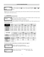
Temperature threshold below which the load is partialized.
Min.
0°C
Max.
15°C
Def. 10 °C
This parameter is displayed only if "Relay 2 and / or relay 3" is/are set to "load."
M
ODBUS
S
ETTINGS
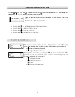
Modbus communication is always active.
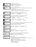
Defines the ModbusRTU address of the adjuster. It can go from 1 to 247.
Def. 1
Defines the transmission speed on channel RS-485
Possible modes:
9600
bps,
19200
bps (Def.),
38400
bps
Defines the type of parity on the serial transmission.
Possibles modes:
None
(Def.),
even
,
odd
Defines the parity bit in the serial transmission.
Possible modes:
1
=one bit (Def.),
2
=two bits
For the Slave mode command with Modbus,
this parameter is for
adjuster’s maximum
time to receive the setting value on Modbus transmission. Over this time the
regulator starts the analog inputs.
Min. 1 Max. 240s
Def. 30s
A
DVANCED SETTINGS
VARIABLE BAND
[WITH CARD S2 and AMBIENT SENSOR CONNECTED]
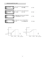
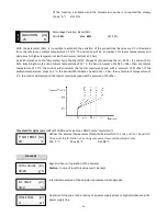
This function, available for operating mode “Chiller-Cool”, adapts the adjustment of the load to the temperature of
the external air so that it is kept stable even with very low external temperatures. Similarly, it allows remaining
around the pressure of maximum performance of the compressor at high temperatures.
Enabling of the variable band funcion.
1
MB ADDRESS [MB]
19200 bps
BAUDRATE [MB]
*
none
PARITY
[MB]
*
BIT STOP
[MB]
*
30
TIME OUT MDB
[IB]
S
S
LA
V
E
10
T° thre.
[IR]
°C
C
H
IL
LE
R
on
BAND VAR.
[IA]
*


