background image

161

FIS Viewer

Diagram information

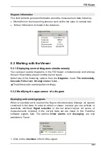
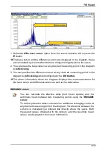
This field contains general information about the measurement data including 

Information on the measuring process such as the low pass or sample rate

 Further information included in the data sets.

5.3 Working with the Viewer

5.3.1 Displaying several diagrams simultaneously

You  can  open  several  diagrams  in  the  FIS  Viewer  simultaneously and  arrange
these in the working area according to your needs. 

Select one  of the  following  options  from  the  

Diagrams

 menu:  

Tile  horizontally

,

Cascade

Full screen

Arrange icons 

or

 List…

.

The windows are rearranged accordingly.

5.3.2 Modifying the appearance of a diagram

Displaying and removing signals

When  a  new  data  set is  opened  the  Viewer simultaneously displays  all  signals
contained  in  the  data.  In  order  to  obtain  a  clearer  overview  you  can  activate  or
deactivate  individual  

Signal  selection

 in  the  list  shown  below.  All  series  of

measurements  included  in  the  current  data  set  are  listed  in  the  Trendline
software  signals  field.  The  options  

Show  alarms

 and  

Averaging

,  are  only

available in Trend.

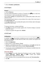
1. Click on the 

checkbox

 in front of the signal.

Summary of Contents for Detector III

Page 1: ...1...

Page 2: ...e may be reproduced or processed duplicated or disseminated w ith electronic systems in any form w ithout our w ritten permission The names and trademarks of the individual companies used in the docum...

Page 3: ...1 1 24 User rights and w riting access 4 1 2 24 Installation Trendline softw are 4 1 3 26 Trendline Setup Wizard 4 1 3 1 28 Detector Flash Updater Setup Wizard 4 1 3 2 28 Database Setup Wizard 4 1 3 3...

Page 4: ...5 1 93 Select database on server 4 5 2 95 Database administration 4 5 3 96 Attach database 4 5 3 1 98 Detach database 4 5 3 2 98 Update database 4 5 3 3 99 Create database 4 5 4 100 Open database 4 5...

Page 5: ...ting and exporting data 137 Export w izard 4 15 1 138 Export a single measuring point 4 15 2 142 Importing data from a Trendline database 4 15 3 144 Export and import templates 4 15 4 145 4 16 Program...

Page 6: ...settings 5 3 12 209 5 4 Keyboard shortcuts 212 6 Detector III 212 6 1 Operation 212 Keypad 6 1 1 214 Sw itching on and off 6 1 2 214 Display and icons 6 1 3 216 6 2 Connectors 217 6 3 Accumulator 218...

Page 7: ...meaning 267 6 15 Update firmware 269 7 Special information 269 7 1 Characteristic values 270 7 2 Frequency selective characteristic values 271 7 3 Time signals 272 7 4 Dynamic memory management 273 7...

Page 8: ...on of alignment errors and imbalance as reliably as roller bearing damage or gearing problems Other process parameters that can be recorded are temperature and rotational speed Applications Measuring...

Page 9: ...he device software guides the user through the balancing process The user can create a configuration for each balancing process with the Trendline software Furthermore he can define templates that can...

Page 10: ...is complied with Moreover the universal safety and accident prevention regulations must be considered Non compliance can endanger the health and life of persons or cause material damage The safety in...

Page 11: ...the danger are explained here Specific hazard symbols DANGER ELECTRICAL SHOCK HAZARD This symbol represents the electrical shock hazard which can lead to personal injury including death or material d...

Page 12: ...elivered CD Rom see General information on vibration monitoring Please read these instructions carefully prior to the start up and keep them in a safe place Ensure that these instructions are availabl...

Page 13: ...ing point with the help of a magnet footing If this is not possible due to the housing material e g aluminum attach an iron plate or a washer the size of the magnetic at the measuring point This is ea...

Page 14: ...ant to part 15 of the FCC Rules These limits are designed to provide reasonable protection against harmful interference when the equipment is operated in a commercial environment This equipment genera...

Page 15: ...10 kHz 20 kHz Highpass demodulation branch 750 Hz Temperature 20 C to 550 C temperature range depends on the used sensor freely configurable input Characteristic values A eff 2 kHz to lowpass RMS val...

Page 16: ...ISO 15693 Product must only be operated in European Union EU Switzerland USA Canada Australia General Separate measurements Temperature rotational speed headset envelope signal Keyboard Membrane keybo...

Page 17: ...able languages German English Finnish French Italian Dutch Polish Portuguese Swedish Slovenian Spanish and Turkish Software FIS Trendline updates on the Internet Available in German English French Por...

Page 18: ...KIT Base unit with accumulator Accelerometer with magnetic foot Infrared temperature sensor Battery charger with travel adapter PC data cable serial USB Manual Protective bag with temperature sensor h...

Page 19: ...gnetic foot and sensor cable Trigger sensor optical and inductive Scales Magnetic holder for trigger sensor Extension stick for magnetic holder Cable for trigger sensor length 10 m Reflex mark for opt...

Page 20: ...e sensor Battery charger with travel adapter PC data cable serial USB Manual Protective bag with temperature sensor holder Trendline PC software Case Accessories Sensor extension cable 5 m and 15 m le...

Page 21: ...vent electromagnetic disturbances from the Detector from affecting other electronic devices nearby From RFID Detector version F4 snap ferrites are no longer needed Attach ferrites Lay the sensor cable...

Page 22: ...rogram installation This chapter describes the installation of the Trendline software The Trendline software requires the MS SQL database server It must be installed either on the local computer or on...

Page 23: ...using a MS SQL database program you can register the CM databases with this You can use the following versions MS SQL Server 2000 requires a commercial license MSDE free version of MS SQL Server 2000...

Page 24: ...ries Using Windows XP SP3 C Users All Users Application Data Condition Monitoring C Users User Local Settings Application Data Condition Monitoring Using Windows 7 64 Bit version C Program Data Condit...

Page 25: ...nstallation types are available Complete setup All software components including databases will be set up on the system Start the installation file Trendline Setup exe with double click The Trendline...

Page 26: ...Trendline software will be described 4 1 3 1 Trendline Setup Wizard 1 Please select the language to install the Trendline software You can change the language settings at any time after installing 2 A...

Page 27: ...atabase 6 and click Next 7 In the next window check your settings and click Install or click Back to correct your settings The Trendline software will be installed 8 Click Finish to exit Trendline ins...

Page 28: ...desktop Create a Quick Launch icon to add a symbol to the Quick Launch bar next to the Start button 4 and click on Next 5 In the next window check your settings and click Install to install the Detec...

Page 29: ...abases are automatically installed demo_online CM database with demo data cm_bearings Bearing database Each new added database will be marked by a sequential number Click Next to proceed with the inst...

Page 30: ...ram on your system Please read the section Database program does not exist Or Select Register databases on an existing SQL Server or MSDE SQL Express if a MS SQL database program see System requiremen...

Page 31: ...hows the name of the server instance that is created 1 Click Next For the installation and administration of the server instance the administrator s password for the user sa is required for more infor...

Page 32: ...ers upper and lower case and alphanumeric and special characters We recommend to note the user defined password in your records 3 Click Next If you selected the installation with databases you can sel...

Page 33: ...the server To access your own database server you need the administrator password The Setup Wizard shows which server instances are already set up on the computer With a new installation from FIS Tre...

Page 34: ...egistration of databases at the server instance the administrator s password for the user sa is required for more information see Users and passwords 3 Enter the administrator password for the server...

Page 35: ...r database s uninstall the Trendline software and run the Trendline setup The Setup Wizard guides you through the installation Update database in the Trendline software If you want to use an existing...

Page 36: ...oftware starts the first time you can configure automatic notifications for software updates If you have set up the Trendline software without database program and databases please select the CM datab...

Page 37: ...ptions and select Update Update settings from the list Under Time interval you can enter how often the Trendline software should check for updates The default setting is weekly If your computer is con...

Page 38: ...isplayed If a firmware update is available the Trendline software also displays the registered Detector devices and the firmware version installed on each device This allows you to quickly recognize w...

Page 39: ...e you can access the various program functions with the different menu bar items Frequently used functions can also be activated using the buttons in the toolbar On the left hand side of the window th...

Page 40: ...t hand side next to the configuration and system structure you can insert an image At the highest level you will find the tab sheets where you can adjust the settings of the individual measuring point...

Page 41: ...complete tree structure Cut Cuts out the current element of the tree Copy Copies the current element of the tree Paste Pastes the element on the clipboard into the current position in the tree This is...

Page 42: ...tes that can be used for free measurements Service E Service Sends selected data for further analysis Measurement report Creates a measurement report Balancing report Creates a balancing report Amplit...

Page 43: ...phase configuration Reset alarm status Add run up coast down configuration Send configuration to Detector Expand selected element Send route template to Detector Collapse selected element Download da...

Page 44: ...ess the key combination CTRL X or click on Left click on the target element and press CTRL V or click on If you want to change the element order within a level select the element by left click and cli...

Page 45: ...dding a sensor Before you can set up configurations you must define the sensors you want to use Detector III is delivered with all necessary sensors They are pre defined in the Trendline software WARN...

Page 46: ...tage in the Detector before the measurement is performed and activates a high pass to filter the supply voltage out of the measuring signal On the other hand the Detector checks whether sensor bias vo...

Page 47: ...ity in mV C mV F or mV K and the offset in mV Click OK to save the new sensor Trigger sensor The trigger sensor serves to measure rotational speed and is used in operational balancing to start the mea...

Page 48: ...stallation of the adapter software To install the adapter software proceed as follows Insert the CD provided The installation program should start automatically If the installation program does not st...

Page 49: ...B to Serial chip please uninstall the drivers for the old devices first as this may result in conflicts Checking serial interface settings To make sure that communication between the Trendline softwar...

Page 50: ...at can be used to enable one unit only Dongle This activation is basically carried out as follows A dongle that has not previously been used is supplied with the balancing kit You can use this dongle...

Page 51: ...at the top The dongle that has been identified is displayed at the bottom The identified version should start with 3 in the case of Detector III The serial number of the Detector for which this dongl...

Page 52: ...0 If Version 1 x is displayed uninstall this driver and install the current driver on the Trendline CD to the CbSetup directory In this case select the CRYPTO BOX USB 4 3 4 Register and configure new...

Page 53: ...hange or by clicking Send system date to the Detector that way the Detector is set to the same time and date as your PC Here you can select the baud rate of the Detector Normally you should select the...

Page 54: ...name of the configuration element must not exceed 49 characters If you have set up templates you can use them for your configurations see Planning with templates and routes Manage configuration elemen...

Page 55: ...to the measuring point using a tape or wire tie The RFID tag Dome is designed especially for metallic foundations and can be glued onto the measuring point When using at temperatures above 85 C you s...

Page 56: ...onfiguration tree Hold the underside of the Detector at the height of the display at a distance of approximately 20 mm as long as quiet above the RFID tag until the measuring point has been measured a...

Page 57: ...nment for each measuring point before the measurement Changing the assignment of an RFID tag To change the assignment of an RFID tag to a measuring point First change the RFID status in the Trendline...

Page 58: ...tector RFID tag assignment handling functions by pressing Esc This preserves the previous state of the assignment If the Detector recognizes an RFID tag that is not in the configuration it displays th...

Page 59: ...ptions In this section you can display and edit the status of an RFID tag assigned to the measuring point and also set up the comment options on the Detector RFID status No RFID No RFID tag is assigne...

Page 60: ...ly want to enter a comment to each measurement Sensor You can adjust the vibration measurement sensors and the temperature at Sensor Only the sensors that were previously entered in the sensor databas...

Page 61: ...rements are performed at the same resolution Apart from Save time signal the time signal settings can no longer be changed after the first measurement as otherwise it would no longer be possible to co...

Page 62: ...also assign bearing data directly to individual measured values For more information refer to Measured values Add bearing to measuring point Click and select a bearing from the bearing database Select...

Page 63: ...enter the speed correction factor SPF and select whether the bearing has a fixed outer race Click on OK Delete selected bearing Click on the bearing to delete and then click Select from which measurem...

Page 64: ...be changed in the bearing database Click on OK Additional kinematic frequencies for analysis In this section you can define additional kinematic frequencies for analysis These are also displayed in th...

Page 65: ...or and Universal Please also observe the information in the Frequency selective characteristic values section Characteristic values can be changed until they have been sent to the Detector for the fir...

Page 66: ...value the both Detector and Trendline software show an Alarm You can also set a pre alarm threshold in Trendline software If the measured value exceeds this threshold the Trendline software will displ...

Page 67: ...without unit To assign later what has been measured with this parameter you should entitle the characteristic value accordingly e g Machine temp C In the Trendline software you can edit the name in th...

Page 68: ...g results in the Trendline software If you edit or create new comments on the Detector this will be added to the measured data in the Trendline software see Measured data The comment list will not be...

Page 69: ...ssign an RFID tag placed on the machine to this measuring point during the next round RFID assigned An RFID tag is assigned to the measuring point The unique ID is displayed in the RFID number field R...

Page 70: ...ere the Detector cannot calculate a suggested test weight Measurement averaging count The Detector averages measured values during the measurement Specify how many values are to be used for averaging...

Page 71: ...e number of possible positions for the balancing weights e g for a fan In addition please enter the angle of the next possible position against the direction of rotation to the reflex mark edge in Ang...

Page 72: ...s Due to the size of the Detector display this can only be 5 characters long BNC connector Select the BNC port used to connect the sensor during the measurement If you are measuring with two sensors y...

Page 73: ...tion The stator is always used as the reference for the zero position which points vertically upwards Select Positive or Negative to indicate whether the measurement should start on a positive or nega...

Page 74: ...each stage of the balancing measurement If you also wish to see the suggested weights and their amplitude and angel or coefficients used and their corresponding amplitude and phase click Show proposed...

Page 75: ...the weights during the trial run and trim run in a circular chart You can switch the display of weights for each plane on or off by clicking on Applied proposed weights Plane n The positions of the w...

Page 76: ...ion To create an amplitude phase configuration click on a Level 3 configuration element e g a machine or motor Then click System Add amplitude phase configuration General settings RFID status No RFID...

Page 77: ...monic 4 3rd harmonic Measuring point tag Enter a name for the measuring points You can change the standard designation MP in the Program settings During the measurement the Detector adds a consecutive...

Page 78: ...he repeated measurement is added to the configuration as a new measuring job The data from the previous measurement are therefore fully retained Example You resend a measuring job to the Detector with...

Page 79: ...nt amplitude and phase of the vibration on the sensor speed as well as data and time The list is sorted in ascending order according to the distance from the referencing point The values are displayed...

Page 80: ...he amplitude and phase of the vibration signals at the measuring points separately over a shared axis that shows the positions of the measuring points to scale Cursor tools In 2D display mode the the...

Page 81: ...he corresponding difference values between the selected measuring points are also shown Rotation The display can be rotated around the x and y axis using the middle mouse button If you also hold down...

Page 82: ...o include the column descriptions and or rotational speed pitch amplitude and phase are always exported Click on Finish to create the file 4 4 9 Set up run up coast down To create an run up coast down...

Page 83: ...e measuring point The unique ID is displayed in the RFID number field Remove RFID This option instructs the Detector to cancel the RFID tag assignment to the measuring point during the next round RFID...

Page 84: ...his is required by the Detector to identify the trigger sensor Due to the size of the Detector display this name can only be five characters long Angle of trigger sensor Enter the angle of displacemen...

Page 85: ...use Hanning windowing when conditioning the measuring signal Hanning windowing leads to better quality of the digitized measuring signal particularly at low rotational speeds However this additional s...

Page 86: ...t comment Below the measurements the window is split into three sections The amplitude phase diagram is displayed in the middle with the diagram editing tools to the left To the right of the diagram t...

Page 87: ...OK Or Click on Enter the name of the frequency band Select the start and end velocity and click OK Deleting a frequency band Click on the frequency band to delete Click on Copying frequency bands to a...

Page 88: ...t the required element from the configuration tree a specific machine for example The alarm values for this element and all sub elements it contains are adjusted Please select or unselect sub elements...

Page 89: ...aries of pre alarm C and main alarm D More information about ISO 10816 classes can be found in the ISO 10816 chapter The values suggested by Trendline for the automatic adjustment of alarm values are...

Page 90: ...r message will be output and the data will not be transferred For more on this see also chapter Frequency analysis see PDF General information on vibration monitoring on the delivered CD Rom 4 5 Trend...

Page 91: ...data storing existing data to a different location using the export function and then deleting the Trendline database 4 5 1 Users and passwords During the installation of the Trendline software the f...

Page 92: ...you use your own SQL server you need the password for this one If you have defined your own password according to your security rules you need this one With user defined passwords maybe you have to u...

Page 93: ...ver where the database is located You have the following options By default the Server name list displays the server instances running on your computer Select an instance Or Click and enter the full s...

Page 94: ...s for the user authentication on the database server Check Use Windows authentication to use your Windows user name and password Or Check Use user name and password and activate Default user and passw...

Page 95: ...lready given the database an alias name it is displayed otherwise the name of the database is including the name of the server Click OK to use the selected CM database 4 5 3 Database administration Wi...

Page 96: ...he database files are still present on your computer but they are not accessible by the database server or the Trendline Software anymore If you want to make a detached database accessible for the Tre...

Page 97: ...ic user name and password and enter your user name and password to log in to the master database Select the Allow saving the password option Select the master database from the database list and click...

Page 98: ...fresh first in order to update the list of available servers Click Use a specific user name and password and enter your user name and password to log in to the master database Select the Allow saving...

Page 99: ...be updated in the database administration click Continue and then Execute The database is updated Click Execute If you try to open a Trendline database that needs to be updated Trendline software off...

Page 100: ...er user name and password if necessary Select a name for the new CM database Click OK The CM database will be created You can find further information to the settings of the database connection dialog...

Page 101: ...Enter an Alias name for the database optionally Click OK The selected CM database can be used You can find further information to the settings of the database connection dialog in the chapter Select...

Page 102: ...atabase The Trendline database provides you with data on the most widely used bearings for use in your individual configuration see Setting up measuring point You can also add your own bearings to the...

Page 103: ...rch you can specify the manufacturer and or group Additionally you can further limit the name of the bearing in Search criterion You can use the wildcards and in the usual way e g 1200 to find all bea...

Page 104: ...a When inputting the contact angle select either degrees or radians for units When specifying the frequencies enter whether these should be in Hz or rpm Trendline indicates whether any information sti...

Page 105: ...for the corresponding bearing as described at Search bearing The list of bearings found is displayed in the Search results as well as the number of hits Select the bearing to be modified and click on...

Page 106: ...ort bearing and search for the bearing you would like to edit as described in Edit delete bearings You can use the Export self created bearings only option to restrict the export to bearings you yours...

Page 107: ...107 Trendline 3 Create a new group To create a new group click on Enter a name for the new group and click OK...

Page 108: ...To delete all bearings from the group click on Click on Save assign the bearings to the group in the bearing database Rename a group To rename a group select it from the Group list and click on Enter...

Page 109: ...turer list and click Continue The manufacturer is then deleted from the bearing database You can only delete manufacturers which have been added by yourself 4 6 8 Select bearing database Click in the...

Page 110: ...ning Click in the Planning menu on Template Click on to add a new template group Name the template group On the Info page you can include a picture with or write a comment in the comment area With you...

Page 111: ...template To edit a template click on the Planning menu on Template Edit the settings as described in Create new template The condition monitoring templates are protected against accidental editing If...

Page 112: ...into a configuration or in several configurations as well you have the option to group parts of those configurations into routes using the Route function For example you could create a route for each...

Page 113: ...figuration to the route You can do that in two different ways Left click in the configuration tree on the element you want to add to the route Next left click in the middle window on the route you wan...

Page 114: ...ates or routes see Template and route planning you can transfer them to the Detector The transfer of a new route or configuration to Detector deletes all data stored on the instrument Click on Detecto...

Page 115: ...g data from the Detector is directly from route planning by selecting Planning Route Click on in the route planning All data i e configurations time signals and free measurements are downloaded to the...

Page 116: ...int that has not yet been sorted in one of the configurations drag it with the left mouse button from the left window onto the measuring point in the configuration If the two really do match the mouse...

Page 117: ...d new configurations sections and machines with the and buttons as you did when creating the configuration For information on this topic see also Enter system structure 4 9 Viewing measuring data 4 9...

Page 118: ...ter field You can use the wildcards and in the usual way e g o Pump to find all measurements containing Pump or o 200 to find all measurements whose comment includes the text 200 at position 2 4 Click...

Page 119: ...sured values Then right click on the selection and on Show FFTs as waterfall graph In the waterfall graph you can view one or more FFTs in different two or three dimensional views or as a sonogram For...

Page 120: ...ring point To apply the bearing information to measurements in a certain time range click Add this bearing to all measurements of following time range and select the time range In the Bearing configur...

Page 121: ...and then This displays the bearing information in the bearing database Further information in Evaluating measured data with the FIS Viewer 4 9 2 Graphic On the Diagram tab Trendline depicts the measu...

Page 122: ...ically Full screen Click on Full screen to scale the graphic to the size of your monitor Filter by comments If you want to display measured data with a particular comment select the option Filter by m...

Page 123: ...se The alarm limits are displayed as colored lines in the diagram The yellow line represents the pre alarm limit the red line the main alarm limit You can adjust the alarm limits directly in the diagr...

Page 124: ...element in the system tree Then click System Reset Alarm Status Only the status display in the system structure is affected when the alarm status is reset The measuring data status displays remain una...

Page 125: ...system messages and additional information on import and export operations are logged If an error occurs during Trendline or Detector operation then an error message is recorded along with additional...

Page 126: ...ded by you the E Services function allows you to send all data necessary to FAG Industrial Services GmbH by e mail Before you begin These services are economical but subject to charge You will find de...

Page 127: ...eate an overview of pre alarms and main alarms accumulated to date for freely selectable elements in your configuration The route report presents all measuring points and corresponding measurement sig...

Page 128: ...ion Select measuring points Trendline displays all available measuring point configurations in the left hand area of the configuration window Select individual measuring points to display the correspo...

Page 129: ...ment select the option Filter by measurement comments Enter the desired comment in the Filter field You can use the wildcards and in the usual way e g o Pump to find all measurements containing Pump o...

Page 130: ...signal FFT In the Time signal FFT area you can specify which time signals are displayed and also whether their corresponding frequencies should be included in the report Click on Time signal or FFT t...

Page 131: ...existing configuration or cancel this operation Create report Click on Preview to create the report The report window opens Trendline outputs a warning if your chosen settings will cause a substantia...

Page 132: ...sed as reference To do this select the element in the configuration tree from which you wish to create the report Click on Service Alarm report or click on in the Toolbar Select the Time range option...

Page 133: ...nter a zoom factor expressed as a percentage in the Percent input field You can navigate forwards or backwards through the report and also jump to the start or end of the report using the arrow button...

Page 134: ...pens You can use the toolbar to control the screen display The display size can be defined in View Select Percent adjustable to enter a zoom factor expressed as a percentage in the Percent input field...

Page 135: ...ed in View Select Percent adjustable to enter a zoom factor expressed as a percentage in the Percent input field You can navigate forwards or backwards through the report and also jump to the start or...

Page 136: ...port using the arrow buttons Click on to print out the report 4 15 Importing and exporting data Import and export between different workstations In Trendline every measuring point in the database has...

Page 137: ...zard in the File menu This launches the Export Wizard which guides you step by step through the export function First select an export file To do so click File name and enter a name Next decide whethe...

Page 138: ...igned to an individual measuring point to a text file to edit them with another program The Trendline software saves the export files in one or several files in CSV format comma separated values i e d...

Page 139: ...Export file with velocity time signal the signal is an acceleration signal see also Time signals Acceleration Export file with the acceleration time signal Demodulation Export file with the demodulat...

Page 140: ...figure and in plain text length Column 1 Internal control index Column 2 Number of FFT lines set in the configuration Ampl Amplifier setting used in the measurement Amplification factor 2Ampl where 0...

Page 141: ...tude of the weight used in plane 1 App weight 1 angle Position angle of the weight used in plane 1 App weight 2 amplitude Amplitude of the weight used in plane 2 App weight 2 angle Position angle of t...

Page 142: ...ring point timestamp Measurement timestamp Comment Measurement comment No data points Number of values measured in run up coast down bodeplot data file File with values from the amplitude phase diagra...

Page 143: ...t at configurations will be overwritten with those from the current database To adopt the default import options click on OK The imported data will be added in the tree view Or Click on Expand to defi...

Page 144: ...ns Click on OK to start the import The imported data will be added in the tree view Import data of Trendline software from version 2 0 x up to 3 0 x Click on File Import Import data from an old databa...

Page 145: ...Accept the default settings Click on OK The templates will be imported to the Trendline software 4 16 Program settings You can open the general program settings configuration window via the Extras Opt...

Page 146: ...and select the dialogue language for the Trendline software System of units setting In this section you can set the units system for the measured values listed The following options are available Sta...

Page 147: ...s Configure the alarm limit settings as described in Adjust alarm limits automatically Comment input on the Detector Here you can specify whether you want to enter a comment for each measurement on th...

Page 148: ...2 Database History Click History In the Number field you can adjust how many entries the list of recently opened databases in the File menu will contain The default value is 10 Memory usage Click on...

Page 149: ...the file name To remove a graphic file again click on Delete 4 16 4 E mail Configuration In order for Trendline to be able to send data by e mail see also E Service or Automatic export you must enter...

Page 150: ...rt only if the data received from the Detector contains alarms File export Click on Automatic to tell the software to export data automatically to a file Click on Only on alarms to perform the automat...

Page 151: ...d the latest trend data from the Trendline software to the Detector The number is limited to a maximum of 10 values The trend data will be send with a configuration to the Detector Click on Settings A...

Page 152: ...nge of navigation tools in the tools working area which can be used to modify the way in which the diagrams are presented and also find a number of different cursor tools for carrying out fault analys...

Page 153: ...can use the Arrange icons button to arrange minimized windows horizontally from left to right in the working area of the Viewer If the Arrange diagrams automatically button is activated the size of th...

Page 154: ...agrams button maximizes all diagram windows The Add additional bearing to the FFT button adds a bearing to the current FFT from the bearing database You can use the Switch back to trendline button to...

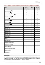
Page 155: ...Difference cursor RMS AMV cursor Harmonics cursor Sideband cursor HS cursor Revolutions cursor Positioning of base cursor Modify cursor properties Copy to clipboard Modifying coordinates of axes Sign...

Page 156: ...diagram in a vertical direction using the Vertical zoom tool The range of values and scaling of the x axis remain unchanged Keyboard zoom You can use the Keyboard zoom feature to enlarge an area of th...

Page 157: ...an spare and the arithmetic mean between two measured values as well as the minimum maximum value Difference cursor FFT time signals Trend data You can use the difference cursor to calculate the diffe...

Page 158: ...properties Opens the cursor properties dialogue window where you can change the properties of the cursor currently used Clipboard Copies an image of the current diagram view into the clipboard additi...

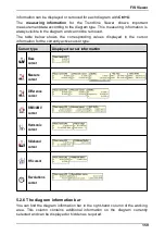
Page 159: ...the corresponding values displayed in the cursor information for the currently active cursor type Cursor type Displayed cursor information Base cursor Measure cursor Difference cursor RMS AMV cursor...

Page 160: ...ncies Information displayed in the diagram information bar Sideband cursor HS cursor Revolutions cursor Diagram information Comments Frequency bands Highest peaks Harmonics Sidebands Kinematic frequen...

Page 161: ...owing options from the Diagrams menu Tile horizontally Cascade Full screen Arrange icons or List The windows are rearranged accordingly 5 3 2 Modifying the appearance of a diagram Displaying and remov...

Page 162: ...e diagram axes to the next 1000 scale 10 Based on the base unit of the diagram for measured values 1 this automatically selects the next smaller unit e g g mg or m mm and inversely for values 1000 the...

Page 163: ...signals more clearly using a logarithmic scale if they do not contain zero values or negative values You can therefore switch over to logarithmic scaling in the diagram 1 Click on the Log checkbox to...

Page 164: ...king the mouse You can adjust the zoom selection setting by right clicking the mouse With the scroll wheel you can zoom and scroll in diagrams Zooming with the scroll wheel If your computer mouse has...

Page 165: ...one of the zoom tools and click on the diagram type whose zoom area you want to change Hold down the Alt key and span the area with the right mouse button The zoom area of all diagrams with identical...

Page 166: ...lick once again on the diagram if you wish to return to the previous zoom selection or 5 To return to the full view of the diagram hold the Shift button down and right click on the diagram Horizontal...

Page 167: ...k on the diagram Vertical zoom You can enlarge an area inside a diagram in a vertical direction using the Vertical zoom tool The range of values and scaling of the x axis remain unchanged 1 Select the...

Page 168: ...Ctrl W buttons to shift the start of the zoom selection 3 Use the Ctrl A and Ctrl S buttons to shift the end of the zoom selection 4 Use the Ctrl Y and Ctrl X buttons to shift the highlighted zoom sel...

Page 169: ...vertical line along the diagram axis keeping the mouse button pressed down Sliding cursors are always represented by a dotted vertical line whereas fixed cursors or automatically calculated data displ...

Page 170: ...ormation above the diagram Measure cursor You can calculate the difference the effective value root mean square and the arithmetic mean between two measuring points with the measure cursor Min max dis...

Page 171: ...values for the base cursor and measure cursor as well as the delta value with frequency minimum maximum values as well as the arithmetic and RMS value for the selected area Calculate spectrum Another...

Page 172: ...s 3 Define overlap 4 Click on OK The spectrogram is shown in the Calculated FFT diagram You can change the display under FFT settings in the work interface area see Waterfall charts Difference cursor...

Page 173: ...clicking while holding down the Shift button The cursor information above the diagram displays the measured values for the base cursor and difference cursor as well as the delta value RMS AMV cursor Y...

Page 174: ...tton with the Shift button pressed down The measured values of the base cursor the averaging cursor as well as the arithmetic and RMS value for the area specified are displayed in the cursor informati...

Page 175: ...rmation above the diagram displays the measured values for the base cursor and the micro increments that were set The measured values of the harmonics are each displayed as vertical text next to the c...

Page 176: ...also modify the position of the sidebands The cursor information above the diagram displays the measured values for the base cursor as well as the differential delta of the sideband frequencies The m...

Page 177: ...ponding vertical line Revolutions cursor The revolutions cursor marks the frequency that is assigned to a specific speed with a line The revolutions value is calculated as follows Revolutions n Rpm 60...

Page 178: ...urrent position of the base cursor If you move the base cursor or position it at another measuring point the speed field moves automatically with it 5 3 6 Positioning of base cursor You can position t...

Page 179: ...perties Using the cursor properties dialogue you can change the properties of the cursor currently selected 1 Click in the toolbar A dialogue showing the currently selected properties of the cursor to...

Page 180: ...ram Switched off the symbols that identify measured values at characteristic points are removed The vertical lines will still be displayed Show units in info boxes This option is only relevant for the...

Page 181: ...ties of the RMS AMV cursor Similarly when using the RMS AMV cursor you can only modify the general cursor options described in Modify the cursor properties To do this activate or deactivate the corres...

Page 182: ...ulated Nearest points The Trendline Viewer calculates the precise mathematic values of the harmonics The intelligent cursor analyses the number of nearest points specified in this field measuring poin...

Page 183: ...es Number of sidebands In this field you can enter the number of sidebands that must be calculated for the current cursor in each case Nearest points The Trendline Viewer calculates the precise mathem...

Page 184: ...nic is determined precisely using a mathematical formula You can enter the number of nearest points to the left and right of the harmonic identified to be analyzed for maximum values The highest value...

Page 185: ...option for the revolutions cursor this is described below To do this activate or deactivate the appropriate fields in the dialogue window or enter the appropriate value in the input field RPM Enter a...

Page 186: ...automatically calculated by the Viewer 3 Select an additional option o Apply settings to the selected diagram only Only the diagram activated in the signal selection see Displaying and removing signal...

Page 187: ...e this tool to change the rotational speed information in an FFT or time signal 1 Click on the Edit rotational speed symbol The Edit rotational speed dialogue is displayed 2 Click on the signal whose...

Page 188: ...rsor selected There are a number of ways in which the diagram information bar can be displayed Adjusting the default setting for the diagram information bar display via the Viewer options The default...

Page 189: ...ed in the right hand field 5 Activate the Show diagram info bar at startup checkbox in the Diagram information bar field The changes are applied the next time this diagram type is opened Displaying th...

Page 190: ...diagram is enabled clicking on a frequency band automatically selects the appropriate signal in the trend diagram Frequency bands are only displayed in FFTs 1 To activate or deactivate a frequency ban...

Page 191: ...tional speed is available for the spectrum see Other Tools Add bearing the FIS Viewer can also display the bearing frequencies in the spectrum 1 Check the Bearing frequencies checkbox to do so 2 Click...

Page 192: ...icking and dragging it To change the allocation of the comment to the measuring point shift on the X axis click on the black triangle for the comment and drag it to the appropriate measuring point Whe...

Page 193: ...harmonics If the Harmonic cursor is selected this diagram information area is displayed The table shows the measured values that most closely correspond to the harmonic The Harmonics table displays th...

Page 194: ...ted values to the clipboard menu item from the context menu 3 Switch to the other application and click the paste symbol or select the Paste menu item from the Edit menu Displaying the measured values...

Page 195: ...ed values to the clipboard menu item from the context menu 3 Switch to the other application and click the paste symbol or select the Paste menu item from the Edit menu Hiding diagram information bar...

Page 196: ...eactivate the Display right diagram information bar at start up checkbox in the Diagram information bar field The changes are applied the next time this diagram type is opened Hiding the diagram infor...

Page 197: ...u can copy measuring data and the content of the diagram information bar to the clipboard to insert it in an other application Modify the diagram appearance and proceed as follows Copy current diagram...

Page 198: ...pboard All diagram information of a selected diagram can be copied to the clipboard Select a diagram by clicking on the diagram windows Click on Copy diagram information to clipboard in the Edit menu...

Page 199: ...e 2D stacked only in case of multiple diagrams The diagrams are displayed two dimensionally with separate axes on top of each other 2D stacked only in case of several diagrams The diagrams are display...

Page 200: ...e order of the curves can be changed by pressing CTRL F 3D Mountains For this type of display the surfaces under the signal curves are displayed in a completed fashion In addition the peaks between th...

Page 201: ...ated as a color value This type of display is especially well suited for comparing a large number of measurements across a long timeframe Here the sonogram makes it easy to recognize whether a machine...

Page 202: ...s In the waterfall diagram you have the same zoom and cursor tools as for two dimensional diagrams for more on this see Zoom tools cursor tools If multiple diagrams are displayed you can select the si...

Page 203: ...e Extras menu Modifying the global settings You can restore the factory settings for the Trendline Viewer using the Global dialogue window status following initial installation of the software Click t...

Page 204: ...ement types are listed Besides the preferred unit and an information about scaling are shown The preferred unit cannot be changed at ISO and US units The automatic scaling is activated by default at t...

Page 205: ...rd You can select the options for transferring the diagrams to the clipboard in the Clipboard dialogue window 1 Select the preferred dimensions for the diagram display in the Diagram width and Diagram...

Page 206: ...the background and also its color 2 In the Integration field you can specify the measuring point in the diagram from which the integration should be performed 3 In the Information bar field you can sp...

Page 207: ...is opened 5 In the Toolbar field you can specify whether Signal selection Axis settings and Zoom tools should be displayed when you open a new diagram 6 In the Trend limitation on load field you can...

Page 208: ...on OK to apply these settings Active signal 1st 5th signal Under the signal options you can modify the display of the individual signals 1 Select a line type for the signal from the drop down menu 2 S...

Page 209: ...L cursor left Moves the basic cursor to the first measuring point in the diagram CTRL cursor right Moves the basic cursor to the last measuring point in the diagram CTRL cursor up Moves the extended c...

Page 210: ...Q Moves the start of the zoom area left CTRL W Moves the start of the zoom area right CTRL A Moves the end of the zoom area left CTRL S Moves the end of the zoom area right CTRL Y Moves the set zoom...

Page 211: ...om the trend display CTRL G Toggle axis view between cascaded and tiled Other keyboard shortcuts Key Function CTRL R Reset comment position CTRL U Show hide right info box at top edge of diagram CTRL...

Page 212: ...via the keys on the membrane keypad The following table explains the meaning of the different keys Key Meaning On off key Switches device on and off Time signal key To display the time signal FFT and...

Page 213: ...e times For example If you want to type in the letter k press the button twice To enter a space character press the button once To set the upper or lower case for a single character select the charact...

Page 214: ...ter the Detector s last action the device automatically shuts down You must switch it back on to perform a new action The power down time can be configured in the system menu If the accumulator is com...

Page 215: ...ine that are not currently visible navigate in the display using the cursor keys and until you see the desired portion of text Icon explanation Several icons are used in the Detector to guide the user...

Page 216: ...ce The headset connection can only be activated via the Single measurements menu 9 pin sub D socket Connection for a serial data line to facilitate exchange of data with the computer RS 232 interface...

Page 217: ...umulator The power supply of the Detector is provided by a removable accumulator The Detector constantly checks the accumulator charge level If the accumulator is not sufficiently charged the device i...

Page 218: ...e temperature The LEDs on the battery charger indicate the charge level Please refer to the battery charger manual for further information Recharge the accumulator regularly even when it is not in use...

Page 219: ...uence as described in the Trendline software help menu You can interrupt the data transfer between Detector and computer at any time by pressing the Esc key The transfer of a new route or configuratio...

Page 220: ...uring point for the balancing measurement Run up coast down Use this menu item to select the run up coast down for determining resonant ranges Amplitude phase Use this menu item to select the amplitud...

Page 221: ...viation was detected The calibration check is password protected If you want to perform a check please contact support fis services com Keep menu position If you choose Yes here the Detector will auto...

Page 222: ...oltage must be at least 3 maximum bias voltage must not be greater than 17 The difference between the two values must not be less than 10 The default setting is min 5 V and max 17 V This values will b...

Page 223: ...s placed with a magnet at the measurement point Therefore the measurement point should have a good metallic contact with bearing and shaft If this is not possible due to the housing material e g alumi...

Page 224: ...ues 6 If you selected the averaging function for this measuring point in Trendline the measurements are repeated according to the number selected a The average value of all FFT values calculated is us...

Page 225: ...le select then the name of the measuring point you have fixed the sensor to using the subsequent menus Then mark Start measurement and confirm your selection using the Enter key Starting the measureme...

Page 226: ...lues After the measurement is complete the measured values are displayed 6 7 3 Display of values measured You can view measured time signals or trends directly once the measurement has been carried ou...

Page 227: ...e of canceling the temperature measurement Press the time signal button to switch to the Time signals or Trend display In the time signal display you can switch to the FFT display In the Detector you...

Page 228: ...st measurement should be saved or discard The measurement is saved Once the characteristic values have been saved the Detector jumps to the Select measuring point menu item to enable you to record dat...

Page 229: ...the cursor key or to switch between the several time signals A horizontal line in the diagram indicates the zero line At the top right side a character is displayed a for acceleration v for velocity...

Page 230: ...orizontal broken line indicates the pre alarm limit In the middle of the window number and type of the characteristic value are displayed Individual measurement points are joined by lines Pressing the...

Page 231: ...ns the same for all screens and zoom factors Press the function button to enable disable auto scaling When switching off auto scaling the zoom factor is set back to 0 1x Top right This character shows...

Page 232: ...ient memory is available If insufficient space is available in the memory for additional time signals these will not be saved even if the option Always save time signals is activated in the configurat...

Page 233: ...n connecting and switching on for initializing the temperature sensor The current temperature value is displayed during the measurement You can accept this value by pressing the Enter button The tempe...

Page 234: ...u do not know the resonance ranges ask the manufacturer or consult the enclosed documents about the resonance range of the device being monitored or determine the resonance range by means of a run up...

Page 235: ...otherwise the Detector shows a Important information If a balancing measurement has been already carried out for a component the Trendline software sends the coefficients of the last trim run to the D...

Page 236: ...ard because the measurement can no longer be assigned to the machine automatically If the coefficients determined after a trial run are used multiple times with different balance weights for the trim...

Page 237: ...g the balancing process Settings You can use this menu item to display the settings you specified for the measuring point in the Trendline balancing configuration You can also restart the balancing me...

Page 238: ...w angles the Detector automatically jumps to the smaller of the two angles so that you can correct your input Example You have a fan with 18 blades the first blade at 0 the second at 20 etc You want t...

Page 239: ...them with a new weight of 19 8 g at 20 Assign RFID Select this menu item to assign an RFID tag placed at the measuring point see Automatic assignment of RFID tags to measuring points In the next step...

Page 240: ...an for example bring the machine to the correct rotational speed before repeating balancing procedure The rotational speed measurement is followed by the reference run 6 8 2 Reference run To perform t...

Page 241: ...run are only saved after you confirm by clicking Values are OK by pressing the Enter button In the table of results click the Esc button to discard the measured values and the Detector returns the Bal...

Page 242: ...of a test weight is counted from the rising or falling edge of the trigger mark depending on which one you selected in the configuration You can check it up in the Balancing menu Settings Trigger sens...

Page 243: ...can select a comment In the comment list you can create a new comment or select an existing one see Managing comments for measurements If no comments exist in the list the edit field for the comment...

Page 244: ...For 1 plane balancing there is only one coefficient while two coefficients are determined per sensor position for two planes Applying balance weights WARNING Damage caused by balancing with weights th...

Page 245: ...use to the vector calculator for example When you click Apply weight again the previous inputs are still there so you can continue at the same point Here again weight positions are counted AGAINST th...

Page 246: ...not improve this is a sign that the influence coefficients are no longer good and that you need to re determine them with a new trial run If the amplitudes measured at all sensor positions in the tria...

Page 247: ...layed in an amplitude phase diagram For the measurement you can specify a rotational speed range to automatically start and stop the measurement Alternatively you can start and stop measuring manually...

Page 248: ...coast down menu item in the Detector Select the measuring point see Selection of measuring point Perform the run up coast down test on the machine Once the desired starting speed has been reached pres...

Page 249: ...e is only an imbalance running down the length of the entire component If you have discovered a critical spot you can narrow it down by performing additional measurements between the two originally me...

Page 250: ...ess the Enter button once amplitude and phase have stabilized after a time After completing the measurement you can select a comment In the comment list you can create a new comment or select an exist...

Page 251: ...onfiguration of the Trendline software In the case of a free measurement you can also modify the settings from here as long as no measurement has been taken General Select this menu item to display th...

Page 252: ...easurements You notice an unusual noise or unusually high temperature on a machine that is not included in this round of measurements You can use the New position option to carry out an additional on...

Page 253: ...d and a cursor is positioned under the first letter Change the name as described in Key pad entries After changing the name select Continue Select Settings to adopt the configuration of the template W...

Page 254: ...evious measurement alternatively In the next menu you can change the template name so that the free measurement can later be assigned to the measuring point at which it was recorded o If you accept th...

Page 255: ...alue for the balancing measurement Balancing OK at is reset to 0 The previous value is no longer applicable for the new balancing unit You should always adjust the limit value in this case otherwise t...

Page 256: ...y pad entries After changing the name select Continue Select Settings to adopt the configuration of the template When carrying out a free measurement all other values can be changed in addition to the...

Page 257: ...ge name and confirm your choice with the Enter button On the next screen the name of the template selected and the current order number are displayed and a cursor is positioned under the first letter...

Page 258: ...d measurements as well as for the ICP sensor test Press on Single measurements in the main menu Please note that single measurements cannot be saved ISO 10816 This menu item allows you to perform a si...

Page 259: ...ithout special foundations rigidly constructed motors and machines up to 300 kW on special foundations III Large motors and other large machines with rotating masses constructed on rigid and heavy fou...

Page 260: ...ition to headset an analog recorder may also be connected to the 3 5 mm jack Measurement with headset is described in more detail in using a headset Temperature The temperature can be measured directl...

Page 261: ...data You can delete the measuring data of a CM balancing run up coast down or amplitude phase measurement on the Detector Therefore select the desired level hall machine or measuring point or mark dir...

Page 262: ...tion Plant Machine Position mark All measurement data of the selected measurement place will be deleted Delete previous measurement data of a configured measurement point Select position Plant Machine...

Page 263: ...ng point is crossed out The current measuring point has a data error You cannot start this measurement If you try to start the measurement the CRC error message is displayed If there are still measure...

Page 264: ...own template has been saved You are trying to perform a free measurement but there is no template is stored in the Detector Templates are only attached if you click in Trendline on Detector Send route...

Page 265: ...able The rotational speed signal is fluctuating Possible causes The trigger sensor is not correctly aligned with the reflex mark The trigger sensor is too close to the reflex mark should be at least 1...

Page 266: ...alancing measurement However observe the information given in balancing measurement Rotational speed to high low for Autostart Autostop Rotational speed already exceeds the selected autostart and or a...

Page 267: ...or to the Trendline software as described at Read measuring data from Detector 2 Download the current firmware file from our website www fis services com 3 Start the Detector FlashUpdater in the start...

Page 268: ...e 4 Prepare the Detector a Switch off the Detector b Insert a thin object a bent open paper clip for example into the small opening on the left hand side of the Detector and hold it in this position u...

Page 269: ...frequency Unit g asel RMS value of acceleration in vibration with freely selectable upper and lower limiting frequency Frequency range 0 1 Hz to 20 kHz depending on the lowpass frequency Unit g deff D...

Page 270: ...cceleration channel a sel Acceleration f min_a lowpass a both frequencies adjustable see table below ISO 10816 Speed 10 Hz 1 kHz v sel Speed f min_v lowpass velocity channel both frequencies adjustabl...

Page 271: ...signals have to be stored at all times For these time signals the right amount of memory is allocated right after the data transfer to ensure that these time signals are guaranteed to be stored Howeve...

Page 272: ...l by the lowpass settings 7 4 Dynamic memory management The Detector offers dynamic memory management Because of this the partitioning of the memory is not defined in the firmware For measuring points...

Page 273: ...ements 7 5 Analog branches in the Detector III Depending on the selected characteristic value the sensor signals are preconditioned by different signal paths in the Detector The measuring signal reach...

Page 274: ...d the last time If not successful it searches for the communication parameters by itself and connects to the Detector If connection is not possible it is due to the following causes The Detector is no...

Page 275: ...adviser Cleaning If necessary you can make an external cleaning of the device Disconnect the accumulator from device Clean the device with a soft lint free cloth CAUTION Damage to the device can resu...

Page 276: ...no longer functions was stored under damage inducing conditions was subject to severe transport stresses Disposal Neither the Detector device nor the associated components may be disposed of via domes...

Page 277: ...nternet www fis services com Further information info fis services com Sales sales fis services com Please send postal mail directly to FAG Industrial Services GmbH Subsidiary of Schaeffler Technologi...

Page 278: ...F4 labelled w ithout RFID meets the requirements w hich have been set by the Electromagnetic Compatibility Directive 2004 108 EG if the product is installed properly according to the installation guid...

Page 279: ...tic Compatibility Directive 2004 108 EG and by the standards on 1999 5 EG R TTE if the product is installed properly according to the installation guidelines listed in the manual For assessment of the...

Page 280: ...decreased since the manufacturing processes can proceed without interruption and under optimal conditions Infrared technology is not a new phenomenon it has been utilized successfully in industrial an...

Page 281: ...e protected from dust and condensing liquids Manufacturers supply the necessary equipment for this Normally only surface temperatures can be measured with the differing emissivities of different mater...

Page 282: ...fore been called infra red after the Latin See Fig 2 Fig 2 The electromagnetic spectrum with range from around 0 7 to 14 m useful for measuring purposes Fig 3 shows the typical radiation of a body at...

Page 283: ...ence the more accurately the IR thermometer works In accordance with the displacement of the radiation maximum to smaller wavelengths with increasing temperature Wien s Displacement Law the wavelength...

Page 284: ...n the infrared range T 0 In accordance with Kirchhof s Law it is assumed that all the radiation absorbed by a body and which has led to an increase in temperature is then also emitted by this body The...

Page 285: ...at a given distance The closer you are to the object or target the smaller the area or spot the probe is sensing For example when the probe is held at a 200 mm 8 in distance from the target the spot...

Page 286: ...he amount of IR energy it receives and the factory set emissivity value of 0 95 which will cover 90 of typical applications Measurement considerations If the surface to measured is small 13 mm in or l...

Page 287: ...Dr Alfred H tthig Verlag Heidelberg 3 VDI VDE Richtlinie Technische Temperaturmessungen Strahlungsthermometrie Januar 1995 VDI 3511 Blatt 4 4 De Witt Nutter Theory and Practice of Radiation Thermomet...

Page 288: ...288...

Page 289: ...ent 87 Alarm limit adjustment reminder 58 146 Alarm limit adjustment w ith the mouse 121 Alias database name 93 Amplitude phase configuration 249 diagram 249 report 134 Analog branches 273 Authenticat...

Page 290: ...ng 104 Comment measurement 68 Comments FIS View er 191 Comments on the Detector 226 Comments edit 213 Comments measurement 117 121 127 Configuration 112 127 Dynamic memory management 272 Measuring poi...

Page 291: ...61 Display 214 215 dow nload log file 125 Dow nload measured data 115 enter comment 226 Info 219 Information 220 Keypad 212 Lighting 212 Measuring procedure 222 Menu 219 Pow er on off 214 register new...

Page 292: ...ram info bar 152 Diagram information 159 Diagram information bar 159 Difference cursor 172 Display several diagrams 161 FFTs Fast Fourier Transformation 152 Frequency bands 190 Harmonic cursor propert...

Page 293: ...ncing report 133 Test measurement 241 245 Import templates 144 Information 11 Installation 22 System requirements 22 ISO 10816 258 ISO units FIS View er 204 K Keyboard shortcuts FIS View er 209 Keypad...

Page 294: ...ctioning 13 Mouse control FIS View er 164 MS SQL database program 22 28 MS SQL database program install 24 Multiple measurements 231 N Names edit 213 Nearest peaks cursor properties FIS View er 179 O...

Page 295: ...91 Safety information 10 sa user 34 Save diagram s FIS View er 197 Scope of delivery 18 Select measuring point 224 Send configuration 90 Send data to E Service 126 Send route template 114 Sensitivity...

Page 296: ...ation 220 Language 220 LCD lighting 219 220 Memory manager 220 Pow er dow n time 222 RFID settings 222 System messages 263 System structure 39 53 T Taking out of service 276 Temperature Characteristic...

Page 297: ...nsor 58 69 82 216 Add 45 Measure rotational speed 239 Trim run 245 U Uninstalling 36 Units FIS View er 204 Universal 269 Universal characteristic value 232 Update Automatic notification 36 150 check f...

Page 298: ...298...

Page 299: ...nside of the battery pack are protected against short circuit by an inner fuse element Generally a short circuit may cause a very strong heating This is to be avoided by all means An inappropriate use...

Page 300: ...al domestic refuse Please return used or damaged batteries to the collecting points provided Charger for FAG Detector battery pack ANSMANN ACS310 The charger is only intended for charging the FAG Dete...

Page 301: ...the battery test phase has finished LED lights green If the LED still keeps flashing red after the test phase the battery pack is faulty and you have to throw it away in a special container for small...

Page 302: ...0 60 Hz Charging current 800 mA 10 Set primary plug The charger is delivered with 4 interchangeable primary plugs and the electronic power supply 100 240 V AC Thus the appliance is worldwide usable Ch...

Page 303: ...en for example Move the plug backwards For use in the USA and Canada Caution Risk of electric shock Dry location use only This power unit is intended to be correctly oriented in vertical or floor moun...

Page 304: ......

Page 305: ......

Page 306: ......

Reviews: