Schaeffler Group Industrial
BA 20
13
Setting the end position
The end position is reached when the rolling bearing has been
moved the displacement distance. The displacement distance can
be read off, for example, in FAG Mounting Manager.
Determining the number of strokes
The number of strokes can be read off on the basis of
the displacement distance and the hydraulic nut used,
Figure 8
,
and the value table, starting from page 24.
Example
The following hydraulic nut is used for mounting of bearings:
■
HYDNUT160.
When using HYDNUT160, any spacer ring present must be
dismounted, see the section Spacer ring, page 9.
The software FAG Mounting Manager determines the displacement
distance as follows:
■
0,94 mm.
The next highest displacement distance is 1,01 mm and the number
of strokes is as follows, see the value table:
■
10 strokes for mounting with hydraulic support
■
12 strokes for mounting without hydraulic support.
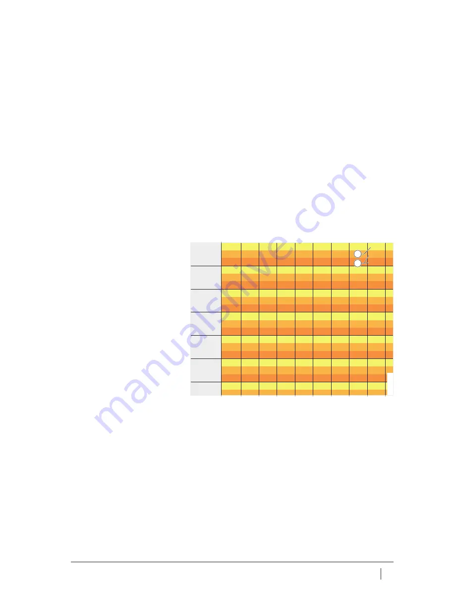
Next highest displacement distance
Number of strokes
Figure 8
Value table, excerpt
160
s
mm
0,52
0,57
0,63
0,69
0,76
0,84
0,92
1,01
1
x
1
–
5
6
6
7
7
8
9
10
11
x
2
–
6
7
7
8
9
10
10
12
13
170
s
mm
0,55
0,61
0,67
0,73
0,81
0,89
0,97
1,07
1
x
1
–
6
6
7
8
9
9
10
11
13
x
2
–
7
7
8
9
10
11
12
13
15
180
s
mm
0,57
0,63
0,69
0,76
0,83
0,92
1,01
1,11
1
x
1
–
7
7
8
9
10
11
12
13
14
x
2
–
8
8
9
10
11
12
13
15
16
190
s
mm
0,61
0,67
0,74
0,81
0,89
0,98
1,08
1,19
1
x
1
–
8
9
10
10
12
13
14
15
17
x
2
–
9
10
11
12
13
15
16
18
19
200
s
mm
0,64
0,7
0,77
0,85
0,94
1,03
1,13
1,25
1
x
1
–
9
10
11
12
13
14
16
17
19
x
2
–
10
11
12
14
15
16
18
20
22
210
s
mm
0,7
0,77
0,85
0,93
1,02
1,13
1,24
1,36
1
x
1
–
11
12
13
14
15
17
19
20
23
x
2
–
12
13
15
16
18
19
21
23
26
220
s
mm
0,7
0,77
0,85
0,93
1,02
1,13
1,24
1,36
1
x
1
–
11
12
14
15
16
18
20
22
24
1
2
00
01
60
64


