background image

(Soft: 01.xx) - 10iE-20iE - Installation/Operation - DRO installation - (27/35)

PAR15

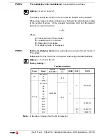
Multi-point leadscrew error compensation.

Important:

Before capturing data for an accuracy graph, the axis (axes) must be
homed (referenced) 

because the compensation will not be applied until they

are homed. To use this compensation, it is recommended to set 

PAR 14

 so

as to force a mandatory home search on power-up.

The compensation point must have at least one point with no error
(error 0).

Multi-point leadscrew error compensation table (in mm)

Point Nr.

Position

Error to be 

compensated

1

0

0

2

200.000

0.002

3

275.250

0.007

4

427.345

-0.005

5

700.500

-0.007

6

760.000

0.003

7

1015.000

0.006

1             2          3               4                       5      6                         7

7
6
5
4
3
2
1
0
1
2
3
4
5
6
7

Summary of Contents for 10iE

Page 1: ...Fagor Automation S Coop 10iE 20iE 10iE B 20iE B Installation Operation Manual Manual code 14460141 Manual version 1104 Software version 1 xx ...

Page 2: ...t centering 10 2 5 3 EDM mode 11 2 5 3 1 Programming the levels 12 3 DRO installation 13 3 1 Installation of the built in model 13 3 2 Rear panel 14 3 3 General technical characteristics 15 3 4 Connections 16 3 4 1 Connection of the feedback systems 16 3 4 2 Input output connection Connector X4 17 3 5 Easy setup 19 3 5 1 Accessing the Easy Setup mode 19 3 5 2 Operating mode 20 3 5 3 Power and mach...

Page 3: ...ey This key togg les the display fo rmat for the rota ry axis between d ecimal degrees and Degrees Minutes Seconds To get into and out of home search mode To access the special function HOLD To select the axis or preset it with a certain value To zero the axis when the quick zeroing mode has been activated see PAR11 in the installation manual To turn the display off while keeping track of the axes...

Page 4: ...r the corresponding error code See the error table and PAR11 for more options Turns the DRO on or off Precautions Before disconnecting this un it from mains press this key so it sa ves the current position If the unit is turned off or there is a power outage the DRO will try to save the current position If it does not have enough time to safe all the data it will display ERROR 2 when turned back o...

Page 5: ...ment of the axis diameter by pressing this key The Φled will t urn on or off to indicate the double or actual reading respectively Notes This works in th is way if bit 2 of installation para meter PAR04 radius diameter of the axis has been preset as 1 commutated Hysteresis or minimum position value When carrying out certain operations such as drilling hard material EDM etc the position display may...

Page 6: ...the home point chosen in the feedback system linear or encoder Press this sequence to access the Home Search mode ABS In Absolute ABS when the ABS led is on it displays the distance from the present position of the axis to part zero D I In Incremental when the ABS and home LEDs are off the distance from the present position of the axis to the previous position is displayed Toggles between the ABS ...

Page 7: ... are using the same machine zero point home Fagor also offers encoders with distance coded reference marks every 20 40 or 100 mm When using these distance coded reference marks there is no need to move to the 0 position to find the references simply move a distance equal to the gap between marks 20 40 or 100 mm depe nding on the linear encoder When using an absolute encoder there is no need to sea...

Page 8: ...ength The Y axis blinks waiting for the tool value to be entered It requests the tool length Enter this value pressing this keystroke sequence Note Since only the length of a tool may be stored when changing a tool its length must be entered again 2 4 2 Absolute and incremental mode We will drill the holes of the following part as moving examples in incremental and absolute modes Value B C A D ...

Page 9: ...e note Move the axis until the display reads 23 000 C position and drill the hole Sets the X axis to zero See note Move the axis until the display reads 25 000 D position and drill the hole Note If installation parameter PAR11 1 just press the axis key X in this case to zero the axis Second method Presetting the relative distance with respect to the next hole Starting at point A Preset the relativ...

Page 10: ... factor 2 5 2 Part centering Note This feature is available when none of the axes have installation parameter PAR04 2 1 radius diameter commutable Part centering can be done as follows Set the dro in absolute mode Touch one side of the part with the tool Set the reading to zero pressing for an axis CLEAR X for one axis or CLEAR Y Z for the other one 20iE Take the tool to the other side of the part...

Page 11: ...e axis reaches the programmed position See next subsection 2 5 3 1 Programming the levels The are two ways to o perate in th is mode depending on the value of installation parameter PAR20 bit 4 PAR20 bit 4 0 the outputs are activated or deactivated when crossing the selected level Home P2 P3 P4 P5 End O1 O2 O3 O4 O5 O6 ...

Page 12: ...output O6 to access them directly The dro displays must be on reading mode and press the following keys The X axis display shows the word COdE 060496 The displays of the DRO show PAR00 Once in regular display mode parameters PAR40 through PAR45 output levels may also be recalled by pressing this keystroke sequence so the work mode may be changed without having to go through all the previous steps ...

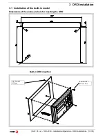
Page 13: ...stallation Operation DRO installation 13 35 3 DRO installation 3 1 Installation of the built in model Dimensions of the enclosure hole for inserting the DRO Built in DRO insertion Bolt ISO 7380 M4 x 10 Inox Nut DIN 985 M4 Inox ...

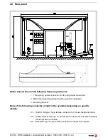
Page 14: ...ection 2 M6 mm terminal for general machine ground connection 3 Mounting bracket Some of the following connectors might not be available depending on specific models X1 SUB D HD type 15 pin female connector for 1st axis feedback device X2 20iE SUB D HD type 15 pin female connector for 2nd axis feedback device scale or encoder X4 SUB D HD type 15 pin female connector for inputs and outputs X4 ...

Page 15: ...ke sure that the unit is not under power It is NOT enough to turn the display off by using the on off key at the keyboard 3 3 General technical characteristics Universal Power Supply between 100V AC and 240V AC 1 0 at Mains frequency between 45 Hz and 400 Hz Between 120Vdc and 300 Vdc It withstands power outages of up to 20 milliseconds 10 year memory backup of installation parameters when the uni...

Page 16: ...consumption 250 mA at the 5V input Admits square wave signal TTL A B Io Maximum frequency 250 KHz minimum gap between flanks 950 nsec Phase shift 90º 20º hysteresis 0 25 V Vmax 7V maximum input current 3mA High threshold logic state 1 2 4V VIH 5V Low threshold logic state 0 0 0V VIL 0 55V Feedback connection Connectors X1 and X2 Pin Signal Function 1 A Input for feedback signals 2 A 3 B 4 B 5 I0 6...

Page 17: ...um voltage 18V DC High threshold voltage logic state 1 18V Low threshold voltage logic state 0 5V Typical consumption of each input 5mA Maximum consumption of each input 7mA Characteristics of the outputs Rated voltage 24 V AC or DC Maximum voltage 47 V AC or DC Over voltage protection Maximum load current 100mA Over current protection Activation time 3ms Deactivation time 3ms Inputs Input output ...

Page 18: ...lation Operation 10iE 20iE Soft 01 xx Outputs The outputs that will be connected to an inductive load must have a 1N4000 diode or similar in anti parallel Open collector outputs Open emitter outputs LOAD Common LOAD LOAD LOAD Common ...

Page 19: ...e installation is correct and no feedback pulses are missed It sets up the encoder resolution and the kind of reference marks being used as well as the positive counting reading direction 3 5 1 Accessing the Easy Setup mode Press CLEAR OFF And instead of entering the parameters accessing code key in 555 The axes displays will show Setup meaning that the feedback is not set up yet CODE 555 ...

Page 20: ...a common point on the machine tool and it to the general ground point Use cables of enough gage no thinner than 8 mm 2 for this connection 3 6 Installation parameters These DROs have a number of insta llation parameters to configure it for a particular application The way th ese parameters are displayed depends on whether they are general or particular for each axis If it affects the axes the para...

Page 21: ... PAR40 45 and PAR53 are directly accessible To enter a parameter Select axis Press this key to save the displayed value Press this key to cancel the modification Move through parameters Press the ENTER key to go on to the next parameter or Press this key to return to the previous one To quit the parameter editing mode Press this key To go to a particular parameter To go directly to a particular pa...

Page 22: ...on units Linear axis 0 mm 1 inches Rotary axis 0 degrees 1 seconds Note These units refer to feedback pulses not to the position display 4 Type of axis 0 Linear 1 Rotary 3 Not being used at this time 2 Not being used it must be set to 0 1 Counting direction 0 normal 1 reverse If an axis count incr eases or decreases in the opposite direction to the one desired change the value of this digit PAR01 ...

Page 23: ... Where p Pulses per turn of the encoder P Leadscrew pitch in mm turn R Resolution in mm pulse F Multiplying factor to be applied PAR03 External multiplying factor when using distance coded reference marks or TTL signals Independent for each axis It is not required when using absolute feedback Options 1 5 10 20 25 50 Factory setting 1 Note In the table X means that the bit is irrelevant p P RxF Fee...

Page 24: ...s parameter will be ignored PAR07 Combine the reading of an axis Independent for each axis Indicates the number of the axis to be combine d 0 means not to combine any other axis 1 X axis 2 Y Z With the ne gative sign the other axis count will be subtracted Factory setting 0 The axis being combined must have the same resolut ion as the one combined with PAR01 PAR02 PAR03 Possible values 2 to 2 20iE...

Page 25: ...e reference point with respect to the reference zero of the scale independent for each axis Usually the machine reference zero reference mark of the linear encoder does not coincide with the absolute zero to be used Therefore when using standard Io s this para meter must be assig ned the value of the distance from the mach ine zero point to the feedback reference point Numeric value in resolution ...

Page 26: ...ff or on If PAR08 bit 2 1 when the axis exceeds the travel distance between both parameters the relevant display starts blinking until it is p ositioned within these limits PAR14 Binary type home search setting Digit 8 7 Not being used at this time they must be set to 0 6 If 1 it indicates mandatory home search on power up 5 Direction of the distance coded Io 0 Increasing 1 Decreasing 4 1 Pitch of...

Page 27: ...lied until they are homed To use this compensation it is recommended to set PAR 14 so as to force a mandatory home search on power up The compensation point must have at least one point with no error error 0 Multi point leadscrew error compensation table in mm Point Nr Position Error to be compensated 1 0 0 2 200 000 0 002 3 275 250 0 007 4 427 345 0 005 5 700 500 0 007 6 760 000 0 003 7 1015 000 ...

Page 28: ...e 7 The displays turn off if none of the axis has moved in 30 minutes Pressing any key or moving any of the axes turns the displays back on 4 0 The outputs are activated or deactivated when crossing the selected level 1 Deactivate the outputs when returning to position home 2 1 Apply hysteresis onto the Y and X axes respectively PAR21 Active level of the inputs Only the first 4 digits have a meani...

Page 29: ...e first digit corresponds to the number of decimals to be displayed in mm and the second digit to the number of decimals in inches When selecting a 0 value or a value greater than the number of decimals of PAR01 it will display the factory set number of decimals Note It has no effect on rotary axes PAR65 It enables various functions of the dro Digit 8 1 To enter the tool length 7 1 To enter the to...

Page 30: ...rical equipment of the machines ELECTROMAGNETIC COMPATIBILITY EN 61000 6 4 Emission EN 55011 Radiated Class A Group 1 EN 55011 Conducted Class A Group 1 EN 61000 3 2 Harmonics EN 61000 3 3 Flickers EN 61000 6 2 Immunity EN 61000 4 2 Electrostatic discharges EN 61000 4 3 Radiofrequency Radiated Electromagnetic Fields EN 61000 4 4 Bursts and fast transients EN 61000 4 5 Shockwaves EN 61000 4 6 Condu...

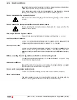
Page 31: ...der to avoid electrical discharges and fire hazards do not apply electrical voltage outside the range indicated in chapter 2 of this manual Ground connection In order to avoid electrical discharges connect the ground terminals of all the modules to th e main ground terminal Before connecting the inputs and outputs of this unit make sure that all the grounding connections are properly made Before p...

Page 32: ...such as Powerful loads connected to the same AC power line as this equipment Nearby portable transmitters Radio telephones Ham radio transmitters Nearby radio TC transmitters Nearby arc welding machines Nearby High Voltage power lines Disturbance generating elements of the machine Etc Safety symbols Symbols which may appear on the manual WARNING symbol It has an associated text indicat ing those a...

Page 33: ...negligence and has been manipulated by personnel authorized by FAGOR If once the service call or repair has been completed the cause of the failure is not to be blamed the FAGOR produ ct the customer must cover all generated expenses according to current fees No other implicit or explicit wa rranty is covered and FAGOR AUTOMATION shall not be held responsible under any circumstances of the damage ...

Page 34: ...round outlets are as they should be If there are OK disconnect the feedback connectors one by one If the dro comes on it mean s a feedback failure If the fau lt persists get in tou ch with Fag or Automation s Customer Services Department about it Error codes Error Description FAGOR dro Power outage or turned off with main switch after saving the data Error 02 The unit has been turned off without p...

Page 35: ...orm or 75 isotropic alcohol with a clean cloth DO NOT USE agg ressive solvents benzol acetones etc which could damage the materials the equipment is made with Do not use high pressure compressed air to clean the item as this could give rise to an accumulation of ch arges which in turn le ad to electrostatic discharges The plastics used in the front panel of the DRO stand up to Grease and mineral o...

Page 36: ...FAGOR AUTOMATION S COOP Bª San Andrés Nº 19 Apdo de correos 144 20500 Arrasate Mondragón Spain Web www fagorautomation com Email info fagorautomation es Tel 34 943 719200 Fa x 34 943 791712 ...

Reviews: