DC Servo Drive System Manual Ver: 0009
DC - 22/32
5.2
ELECTRICAL CONNECTIONS
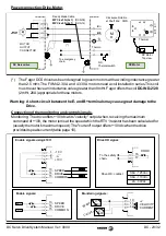
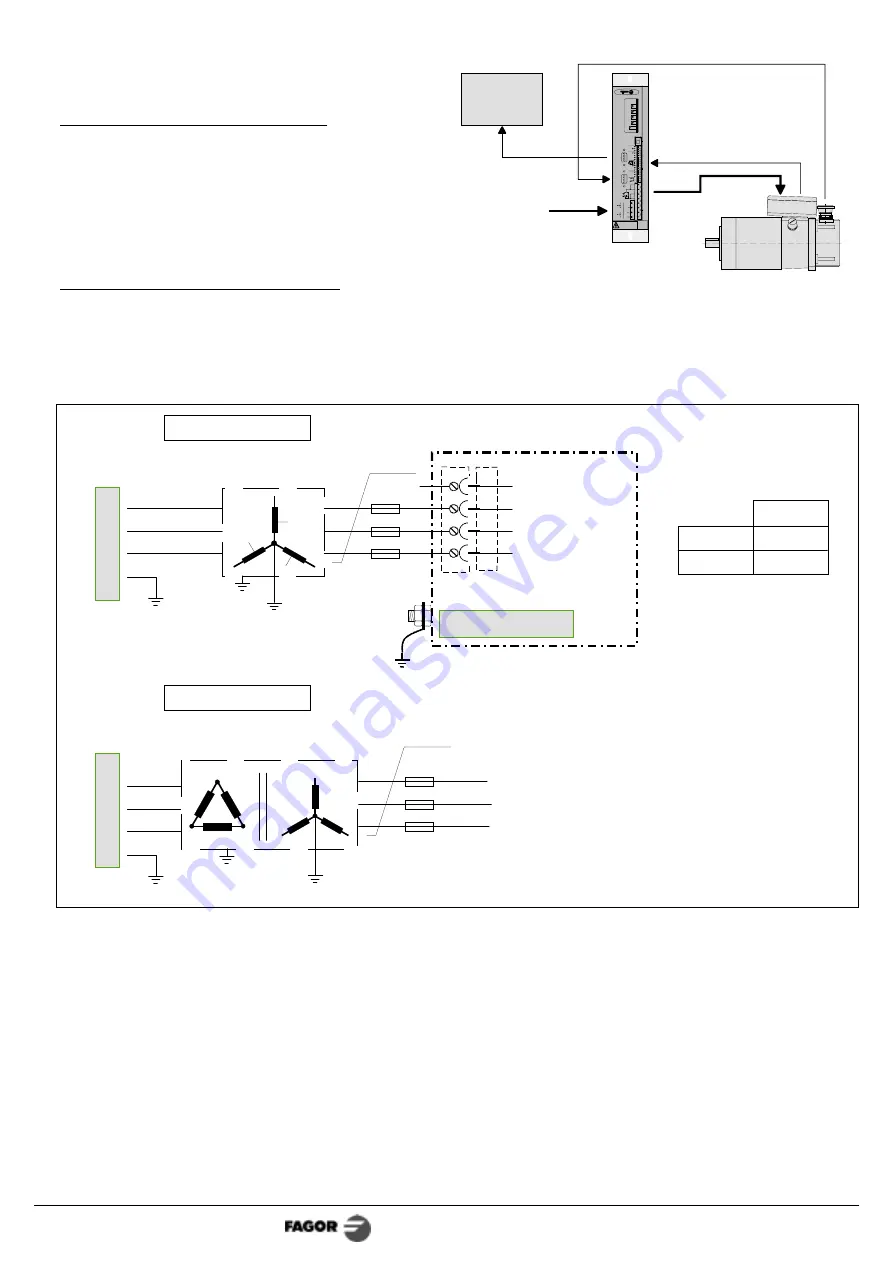
Basic interconnection diagram
Power connection: Mains-Drive.
The drive power supply must be three-phase. A transformer MUST BE used. It must be used to
filter the start-up current to the maximum value allowed by the unit.
See characteristics on page 10.
(*) Recommended values. They are slow general purpose fuses. If they are installed on the Mains
input lines, their maximum currents will depend on the value of the Mains voltage.
Cartridges 5SE0 016-OY and 5SE0 020-OY from Siemens are good for this application.
A thermal switch may optionally replace the fuses.
Important: The secondary windings must have a star connection with its middle point connected
to ground.
POWER
INPUT
L3
L1
L2
Autotransformer.
DC Servodrive
P
o
we
r M
a
in
s
3 x 2.5 mm
2
Fuses
Secondary: 3x110 Vac
From 1.7 to 3 kw
DCS-08
DCS-14
10 Amp
16 Amp
Secondary: 3x110 Vac
Transformer.
Fuses
From 1.7 to 3 kw
3 x 2.5 mm
2
P
o
we
r M
a
in
s
Fuses (*)
Not connected
Ac c/De c.
Ra m ps
M ax .
Cu r re nt
L im it
PI.G ain
. DRIVE
DISA BLED
0 SPEED DISA BLED
1 RUNNING
2 MO TO R ISO LATION FAULT
3 FEEDBACK ERROR
4 DRIVE OVERTEMPERATURE
5 MO TO R OVERLOAD
6 DRIVE OVERCURRENT
7 DRIVE OVERVOLTAGE
E UNDERVOLTAGE
M ax .
Sp eed
Of fs et
ADJ
U
S
T
DC S
e
rvo
d
ri
v
e
S
T
AT
US
CO
NT
RO
L
-
S
IG
NAL
S
PO
W
E
R
T
E
R
M
IN
A
L
S
E
NCO
DE
R
OU
T
P
U
T
E
NCO
DE
R
IN
P
U
T
SPEED
CURRENT
SPEED
DRIVE
EN
A
B
L
E
S
±
1
0
V
DR.
OK
17
16
15
14
13
12
11
10
9
8
7
6
5
4
3
2
1
COMMON
DIFF-
CURRENT
DIFF+
+1 0V
-10 V
20
mA
o
u
t
M OTO R
O UTPUTS
PO WER INP UTS
1
1
0
Va
c
. I
N
PU
T
3x110V
ac.
I
N
P
U
T
L1
L4
L3
L2
DANGER
HIG H VO LTAG E 1 5 0 Vdc
DISC HA RGE TIM E > 1 m in.
M
T
CNC
Mains
DCS
DCM
DCTC Cable
DCEC Cable
MPC Cable
SEC Cable


