Chapter 3 - page 44
MC work mode
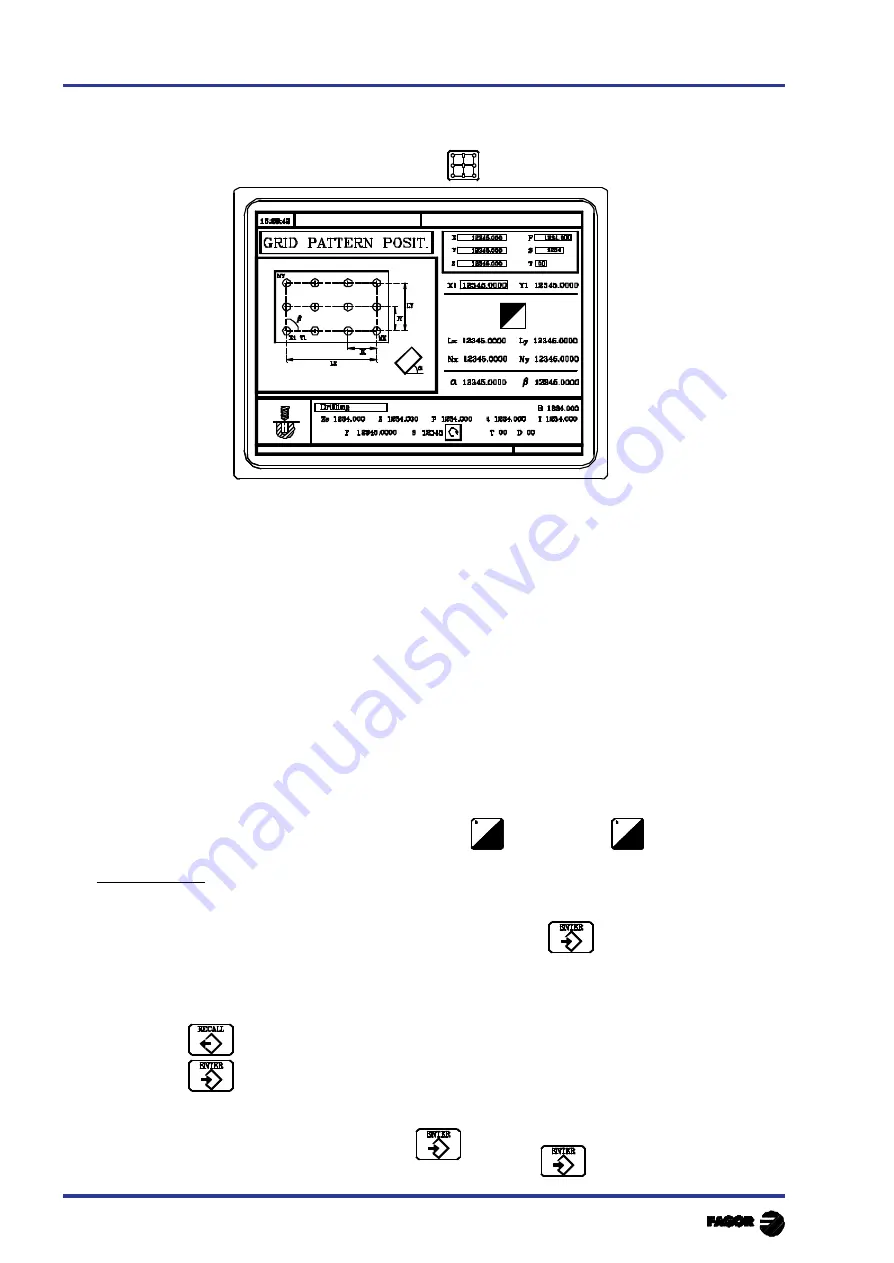
3.13.5 MULTIPLE POSITIONING IN A GRID PATTERN
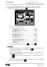
To associate this positioning with an operation, press
This could be defined in 3 different ways:
1)
The coordinates of the first point ..........................................(X1, Y1)
The lengths in X, Y ............................................................. (Lx, Ly)
The X and Y distances between points ................................... (Ix, Iy)
The rotation angle .......................................................................(
α
)
The angle between the sides ........................................................ (
β
)
2)
The coordinates of the first point ..........................................(X1, Y1)
The lengths in X and Y ........................................................ (Lx, Ly)
The number of points in X and Y ........................................ (Nx, Ny)
The rotation angle .......................................................................(
α
)
The angle between the sides ........................................................ (
β
)
3)
The coordinates of the first point ..........................................(X1, Y1)
The X and Y distances between points ................................... (Ix, Iy)
The number of points in X and Y ........................................ (Nx, Ny)
The rotation angle .......................................................................(
α
)
The rotation angle ....................................................................... (
β
)
To select the desired one, place the cursor over the
icon and press
Point definition
The coordinates are defined one by one. After placing the cursor over the axis coordinates, one can:
a) Enter the value by hand. Key in the desired value and press
b) Assign the current axis position.
Jog the axis to the desired point with the handwheel or the JOG keys. The upper right-hand window
shows the tool position at all times.
Press
for the selected data to assume the value shown in the upper right-hand window.
Press
To define the rest of the values (Lx, Ly, Ix, Iy,
α
,
β
, Nx, Ny), place the cursor in the corresponding
window, key in the desired value and press
3.
Work with operations and cycles
3.13
Multiple positioning
3.13.5 Multiple positioning in a grid pattern
Summary of Contents for 8040 CNC - FEATURES
Page 1: ...REF 0307 SOFT M 7 XX SOFT M 7 1X 8040 CNC NEW FEATURES ...
Page 2: ...Page 2 of 2 8040 CNC NEW FEATURES SOFT M 7 XX SOFT M 7 1X ...
Page 45: ...User notes NEW FEATURES SOFT M 7 XX Page 41 of 48 8040 CNC ...
Page 46: ...User notes NEW FEATURES SOFT M 7 XX Page 42 of 48 8040 CNC ...
Page 52: ...User notes NEW FEATURES SOFT M 7 1X Page 48 of 48 8040 CNC ...
Page 53: ...Operating Manual MC option Ref 0204 ing ...
Page 143: ...Self teaching Manual MC option Ref 0112 ing ...
Page 147: ...Chapter 1 Theory on CNC machines ...
Page 156: ...Chapter 2 Theory on tools ...
Page 164: ...Chapter 3 Hands on training ...
Page 186: ...Chapter 4 Automatic Operations ...
Page 201: ...Chapter 5 Summary of work cycles ...
Page 220: ...Chapter 6 Conversational part programs ...
Page 235: ...Appendix I Programming example ...
Page 237: ...Self teaching Manual Appendix I Page 3 MC Model Programming example Step 1 Surface milling 1 ...
Page 239: ...Self teaching Manual Appendix I Page 5 MC Model Programming example Step 3 Rectangular boss 3 ...
Page 240: ...Self teaching Manual Appendix I Page 6 MC Model Programming example Step 4 Circular pocket 4 ...


