·326·
Programming manual
CNC 8055
CNC 8055i
12.
PROBING
·M· & ·EN· M
ODELS
S
OFT
: V02.2
X
PROBE 10
. Rectang
ula
r pa
rt centerin
g ca
nne
d cycl
e
12.12
PROBE 10. Rectangular part centering canned cycle
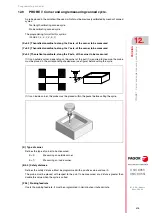
Cycle that, with a digital probe, minimizes the preparation time of rectangular part calculating the
real coordinates of the center, of the surface and of the part inclination.
(PROBE 10, I, J, X, Y, Z, K, L, B, D, E, H, F, Q)
Initial conditions
• The probe must properly calibrated in radius and length.
• The probe position before the first probing movement must be as centered as possible in X and Y.
Considerations for the cycle
• After the probing movements, the probe withdraws from the part in G0 before moving to the safety
Z position.
• Depending on the PRBMOD variable, no error is issued in the following cases, even if machine
parameter PROBERR=YES.
When a G75 probing move finishes before the probe has touched part.
When a G76 probing move finishes but the probe is still touching the part.
Parameters
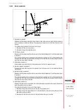
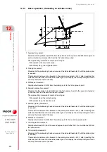
[ X±5.5 ] X coordinate where probing will begin
X coordinate of the probe position where the first probing move will start.
If not programmed, it will assume the current X position of the probe.
[ Y±5.5 ] Y coordinate where probing will begin
Y coordinate of the probe position where the first probing move will start.
If not programmed, it will assume the current Y position of the probe.
[ Z±5.5 ] Z coordinate where probing will begin
Z coordinate of the probe position where the first probing move will start.
If not programmed, it will assume the current Z position of the probe.
[ I5.5 ] X length of the rectangular part.
If not programmed or programmed with a 0 value, it generates the corresponding error message.
[ J5.5 ] Y length of the rectangular part.
If not programmed or programmed with a 0 value, it generates the corresponding error message.
[ K1 ] Axis and direction of the first probing movement.
The values are:
• For X+ : 0
• For X- : 1
• For Y+ : 2
• For Y- : 3
If not programmed, it assumes 0.
[ L1 ] It indicates whether the part surface is measured or not
• Value 0: It is not measured
• Value 1: It is measured
• If not programmed, a value of 0 is assumed
Summary of Contents for 8055 EN
Page 1: ...CNC 8055 M EN Programming manual Ref 1711 Soft V02 2x...
Page 8: ...8 Programming manual CNC 8055 CNC 8055i SOFT V02 2X...
Page 12: ...12 CNC 8055 CNC 8055i Declaration of conformity and Warranty conditions...
Page 16: ...16 CNC 8055 CNC 8055i Version history...
Page 22: ...22 CNC 8055 CNC 8055i Returning conditions...
Page 24: ...24 CNC 8055 CNC 8055i Additional notes...
Page 26: ...26 CNC 8055 CNC 8055i Fagor documentation...
Page 448: ......
Page 464: ...464 Programming manual CNC 8055 CNC 8055i D M EN MODELS SOFT V02 2X Key code...
Page 466: ...466 Programming manual CNC 8055 CNC 8055i D M EN MODELS SOFT V02 2X Key code MC operator panel...
Page 467: ...Programming manual CNC 8055 CNC 8055i D M EN MODELS SOFT V02 2X 467 Key code...
Page 468: ...468 Programming manual CNC 8055 CNC 8055i D M EN MODELS SOFT V02 2X Key code...
Page 471: ...Programming manual CNC 8055 CNC 8055i D M EN MODELS SOFT V02 2X 471 Key code 11 LCD Monitor...
Page 472: ...472 Programming manual CNC 8055 CNC 8055i D M EN MODELS SOFT V02 2X Key code...
Page 478: ...478 Programming manual CNC 8055 CNC 8055i F M EN MODELS SOFT V02 2X Maintenance...
Page 479: ...Programming manual CNC 8055 CNC 8055i F SOFT V02 2X 479...
Page 480: ...480 Programming manual CNC 8055 CNC 8055i F SOFT V02 2X...
Page 481: ......


