·196·
Programming manual
CNC 8055
CNC 8055i
9.
CANN
ED
CYCLES
·M· & ·EN· M
ODELS
S
OFT
: V02.2
X
G2
10. Bo
re mi
llin
g ca
nne
d cycl
e
9.16
G210. Bore milling canned cycle
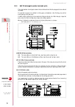
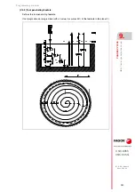
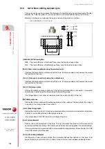
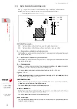
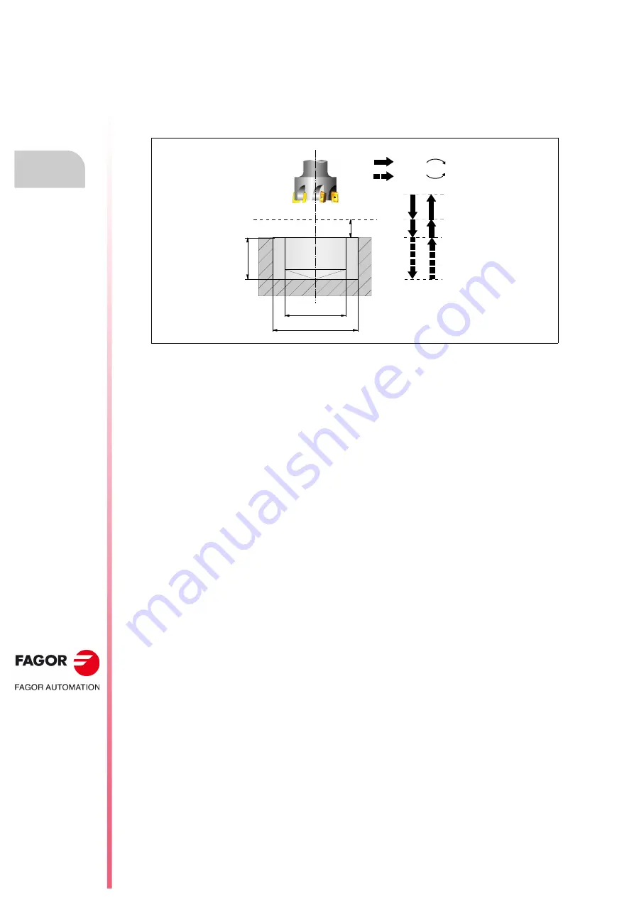
This cycle may be used to increase the diameter of a hole through a helical movement of the tool.
Besides this, if the tool allows it, it is also possible to mill a hole without having to drill it first.
Working in Cartesian coordinates, the basic structure of the block is as follows:
G210 G98/G99 X Y Z D I J K B
[ G98/G99 ] Withdrawal plane
G98
The tool withdraws to the Initial Plane, once the hole has been milled.
G99
The tool withdraws to the Reference Plane, once the hole has been milled.
[X±5.5] Hole center coordinate along the abscissa axis.
It defines the hole center coordinate along the X axis. If not programmed, it will assume the current
tool position on that axis.
[ Y±5.5 ] Hole center coordinate along the ordinate axis
It defines the hole center coordinate along the Y axis. If not programmed, it will assume the current
tool position on that axis.
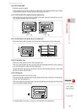
[ Z±5.5 ] Reference plane
Defines the reference plane coordinate. It may be programmed either in absolute or incremental
coordinates, in which case it will be referred to the starting plane.
If not programmed, it assumes as reference plane the current position of the tool.
[D5] Safety distance
Defines the distance between the reference plane and the surface of the part where the milling is
to be done. If not programmed, it assumes 0.
[ I±5.5 ] Machining depth
Defines the machining depth. It may be programmed either in absolute or incremental coordinates,
in which case it will be referred to the reference plane.
If not programmed, the CNC issues the corresponding error.
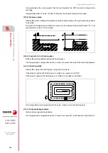
[J±5.5 ] Hole diameter
Defines the nominal diameter of the hole. The sign indicates the direction of the helical path
associated with the machining of the hole (positive if clockwise and negative if counterclockwise).
If not programmed or programmed with a value smaller than the diameter of the active tool, the CNC
issues the relevant error message.
[ K5.5 ] Pre-drilling diameter
Starting with a hole previously drilled, this parameter defines the diameter of that hole. If not
programmed or programmed with a 0 value, it means that no hole has been previously drilled.
G98
G99
I
K
Z
D
J
G00
G01
M03
M04
Summary of Contents for 8055 EN
Page 1: ...CNC 8055 M EN Programming manual Ref 1711 Soft V02 2x...
Page 8: ...8 Programming manual CNC 8055 CNC 8055i SOFT V02 2X...
Page 12: ...12 CNC 8055 CNC 8055i Declaration of conformity and Warranty conditions...
Page 16: ...16 CNC 8055 CNC 8055i Version history...
Page 22: ...22 CNC 8055 CNC 8055i Returning conditions...
Page 24: ...24 CNC 8055 CNC 8055i Additional notes...
Page 26: ...26 CNC 8055 CNC 8055i Fagor documentation...
Page 448: ......
Page 464: ...464 Programming manual CNC 8055 CNC 8055i D M EN MODELS SOFT V02 2X Key code...
Page 466: ...466 Programming manual CNC 8055 CNC 8055i D M EN MODELS SOFT V02 2X Key code MC operator panel...
Page 467: ...Programming manual CNC 8055 CNC 8055i D M EN MODELS SOFT V02 2X 467 Key code...
Page 468: ...468 Programming manual CNC 8055 CNC 8055i D M EN MODELS SOFT V02 2X Key code...
Page 471: ...Programming manual CNC 8055 CNC 8055i D M EN MODELS SOFT V02 2X 471 Key code 11 LCD Monitor...
Page 472: ...472 Programming manual CNC 8055 CNC 8055i D M EN MODELS SOFT V02 2X Key code...
Page 478: ...478 Programming manual CNC 8055 CNC 8055i F M EN MODELS SOFT V02 2X Maintenance...
Page 479: ...Programming manual CNC 8055 CNC 8055i F SOFT V02 2X 479...
Page 480: ...480 Programming manual CNC 8055 CNC 8055i F SOFT V02 2X...
Page 481: ......

