·290·
Programming manual
CNC 8055
CNC 8055i
12.
PROBING
·M· & ·EN· M
ODELS
S
OFT
: V02.2
X
PROBE 1. Too
l leng
th
cal
ibratin
g ca
nne
d cycl
e
12.3.1
Calibrate the length or measure the length wear of a tool.
The type of operation (calibration or measurement) is selected when calling the cycle.
The calibration or measurement may be done on the tool shaft or on its tip. It is selected when calling
the canned cycle.
The programming format depends on the operation to carry out:
• Tool length calibration along its shaft.
(PROBE 1, B, I0, F, J0, X, U, Y, V, Z, W)
• Tool length calibration at its tip.
(PROBE 1, B, I1, F, J0, D, S, N, X, U, Y, V, Z, W)
• Measurement of the tool length wear along its shaft.
(PROBE 1, B, I0, F, J1, L, C, X, U, Y, V, Z, W)
• Measurement of the tool length wear at its tip.
(PROBE 1, B, I1, F, J1, L, D, S, C, N, X, U, Y, V, Z, W)
[ B5.5 ] Safety distance
It must be programmed with a positive value greater than 0.
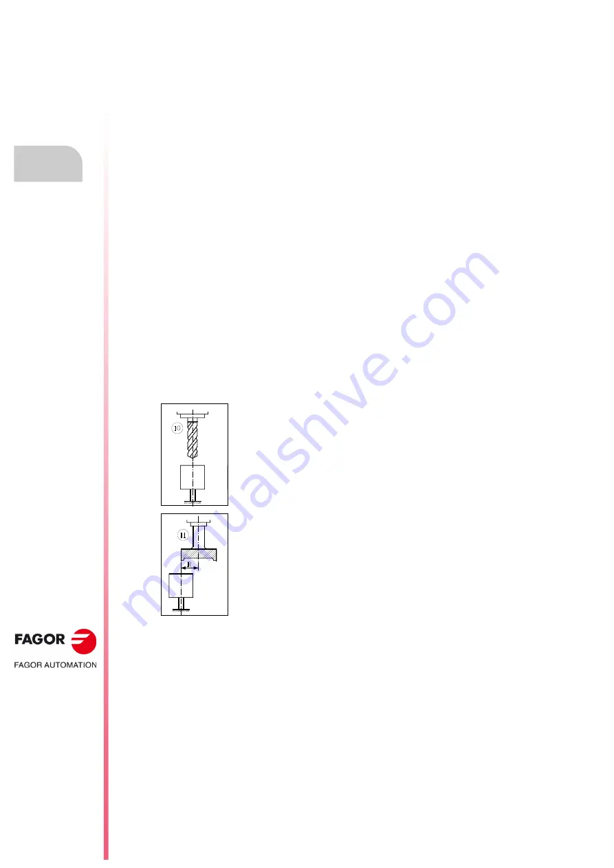
[ I ] Type of calibration or wear measurement
The calibration may be done on the tool shaft or on its tip.
I = 0
Calibration of the tool length or measurement of the tool length wear along its
shaft.
I = 1
Calibration of the tool length or measurement of the tool length wear on its tip.
If not programmed, the cycle will assume the IO value.
[ F5.5 ] Probing feedrate
It sets the probing feedrate. It must be programmed in mm/minute or inches/minute.
[ J ] Type of operation
The calibration may be done on the tool shaft or on its tip.
J = 0
Tool calibration.
J = 1
Tool wear measurement.
[ L5.5 ] Maximum length wear allowed
When set to zero, the tool will not be rejected due to length wear. When the measured wear is greater
than the defined value, the tool will be rejected.
Only if J1 has been defined and tool life monitoring is being used. If not programmed, the canned
cycle will assume the L0 value.
I = 0. Tool calibration along its shaft.
It is useful for drilling tools, ball end-mills, or tools whose diameter is smaller
than the probe's probing surface.
This type of calibration is carried out with the spindle stopped.
I = 1. Tool calibration at its tip.
It is useful for calibrating tools with several cutting edges (end-mills), or tools
whose diameter is larger than the probe's probing surface.
This type of calibration may be carried out either with the spindle stopped or
turning in the opposite direction to the cutting direction.
Summary of Contents for 8055 M
Page 1: ...CNC 8055 M EN Programming manual Ref 1711 Soft V02 2x...
Page 8: ...8 Programming manual CNC 8055 CNC 8055i SOFT V02 2X...
Page 12: ...12 CNC 8055 CNC 8055i Declaration of conformity and Warranty conditions...
Page 16: ...16 CNC 8055 CNC 8055i Version history...
Page 22: ...22 CNC 8055 CNC 8055i Returning conditions...
Page 24: ...24 CNC 8055 CNC 8055i Additional notes...
Page 26: ...26 CNC 8055 CNC 8055i Fagor documentation...
Page 448: ......
Page 464: ...464 Programming manual CNC 8055 CNC 8055i D M EN MODELS SOFT V02 2X Key code...
Page 466: ...466 Programming manual CNC 8055 CNC 8055i D M EN MODELS SOFT V02 2X Key code MC operator panel...
Page 467: ...Programming manual CNC 8055 CNC 8055i D M EN MODELS SOFT V02 2X 467 Key code...
Page 468: ...468 Programming manual CNC 8055 CNC 8055i D M EN MODELS SOFT V02 2X Key code...
Page 471: ...Programming manual CNC 8055 CNC 8055i D M EN MODELS SOFT V02 2X 471 Key code 11 LCD Monitor...
Page 472: ...472 Programming manual CNC 8055 CNC 8055i D M EN MODELS SOFT V02 2X Key code...
Page 478: ...478 Programming manual CNC 8055 CNC 8055i F M EN MODELS SOFT V02 2X Maintenance...
Page 479: ...Programming manual CNC 8055 CNC 8055i F SOFT V02 2X 479...
Page 480: ...480 Programming manual CNC 8055 CNC 8055i F SOFT V02 2X...
Page 481: ......


