AC Brushless Servo Drive System Manual Ver: 0002
ACa - 28 / 32
Preliminary
5.3
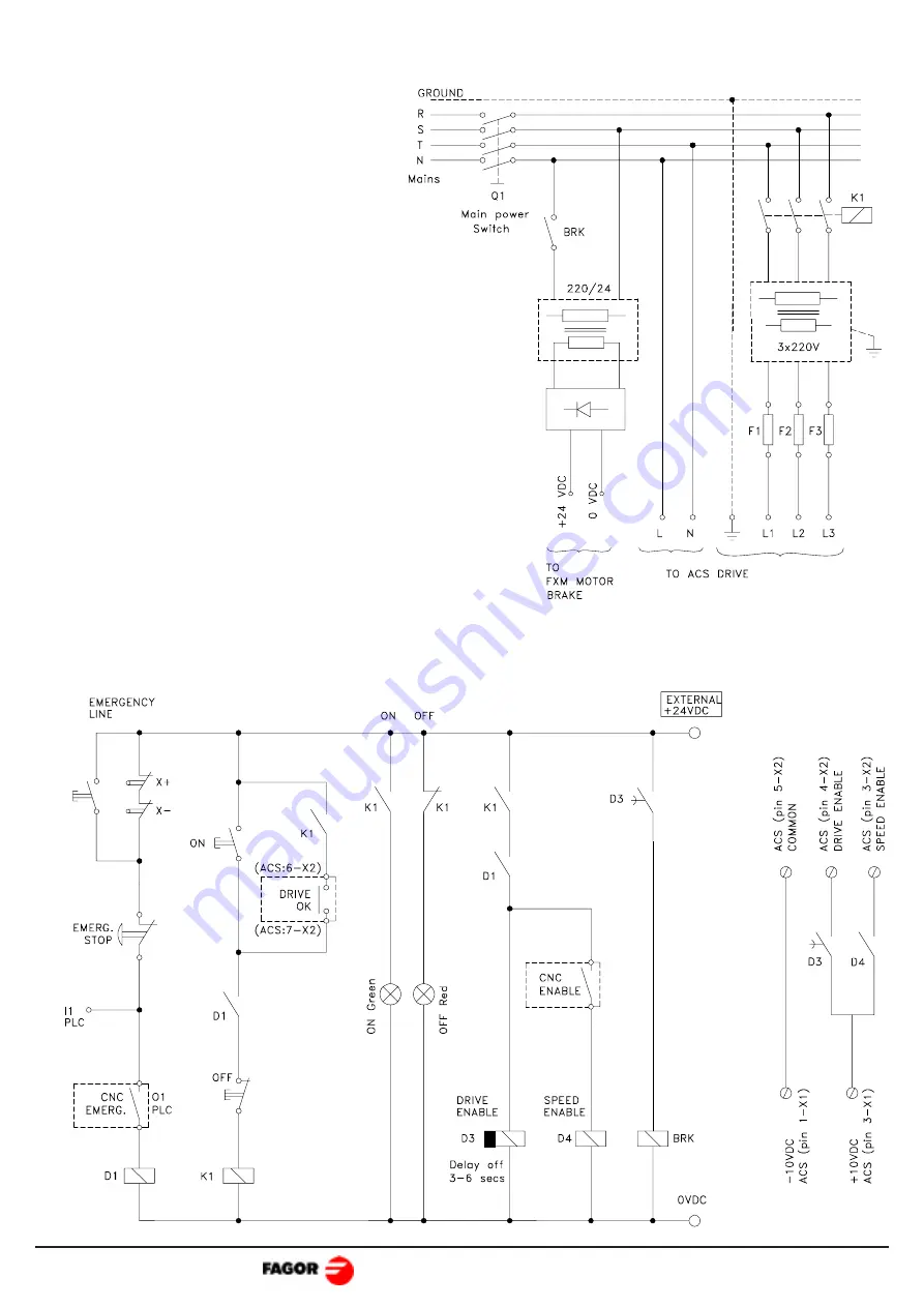
ELECTRICAL ENCLOSURE DIAGRAM
This is a sample diagram for an
electrical enclosure. It may be
modified to meet the needs of a
particular application.
It includes a simple circuit to power
the brake of the FXM.
Warning: When using an
autotransformer, the secondary must
have a star connection with its
middle point connected to ground.
Fuses are MANDATORY.
The delay when disconnecting the D3 contacts
serves for:
- the "Drive_Enable" to stay active while the motor
is braking at maximum torque.
- for the brake to hold the motor after it has
stopped.
If the system moves a vertical axis, it should be
compensated for (with counterweight).


