Drive modules
DRIVE MODULES
Mo
dula
r d
riv
es
3.
125
DDS
HARDWARE
Ref.1310
Other elements
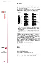
Besides the various connectors, the front panel of the drive has other ele-
ments that are mentioned next.
Fuse
The fuse on the front panel of each modular drive is a “2.5 A (F)/250 V
(fast)” fuse and it is used to protect the internal control circuits.
Status display
The seven-segment status display shows the information on the drive
module status or the corresponding code when an error or warning oc-
curs - see the section “turning a drive on” at the end of this chapter -
. It can also display the transmission speed when setting it both with SER-
COS or CAN interface.
FUSE
2,5A(F)
(250V)
STATUS
DISPLAY
Summary of Contents for APS-24
Page 1: ...DRIVE DDS Hardware manual Ref 1310...
Page 6: ...I 6 DDS HARDWARE Ref 1310...
Page 9: ......
Page 10: ......
Page 11: ......
Page 12: ......
Page 16: ...16 Ref 1310 DDS HARDWARE...
Page 30: ...1 DESCRIPTION 30 Description DDS HARDWARE Ref 1310...
Page 94: ...2 POWER SUPPLIES 94 Power supplies DDS HARDWARE Ref 1310...
Page 188: ...3 DRIVE MODULES 188 Drive modules DDS HARDWARE Ref 1310...
Page 204: ...4 AUXILIARY MODULES 204 Auxiliary modules DDS HARDWARE Ref 1310...
Page 232: ...SELECTING CRITERIA 5 232 Selection criteria DDS HARDWARE Ref 1310...
Page 266: ...7 CABLES 266 Cables DDS HARDWARE Ref 1310...
Page 312: ...8 INSTALLATION 312 Installation DDS HARDWARE Ref 1310...
Page 326: ...9 FUNCTIONAL SAFETY 326 Functional safety DDS HARDWARE Ref 1310...
Page 354: ...10 CONNECTION DIAGRAMS 354 Connection diagrams DDS HARDWARE Ref 1310...
Page 378: ...12 SALES REFERENCES 378 Sales references DDS HARDWARE Ref 1310...
Page 384: ...13 COMPATIBILITY 384 Compatibility DDS HARDWARE Ref 1310...
Page 385: ......


