background image


02/05/2020 


32 


SERVICE MANUAL 


CONVEYOR BELT 
DISHWASHERS


water inlet hose to 

A+F.


Install a shut-off valve on the water supply close to the machine in an accessible position. 


A filter must be installed after the shut-off valve and before the appliance and should be easily accessible 

for cleaning. 


Check that the mains pressure is within the range indicated above. 


Check that there are no leaks. 


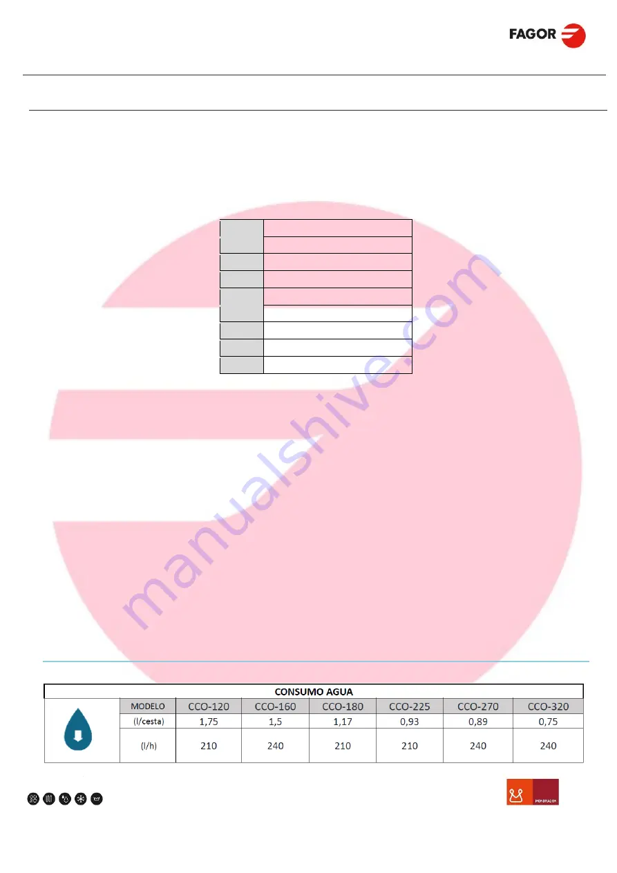
The hydraulic circuit guarantees a stable consumption in the event of changes in pressure in the mains. The water 

input pressure to the machine should be 2 to 4 bar. Therefore, the rinse water control pressure must be adjusted to the 

following pressures: 


CCO-120 -> 0.7 bar -> 210 L/h 


CCO-160 -> 0.9 bar -> 240 L/h 


CCO-180 -> 0.7 bar -> 210 L/h 


CCO-225 -> 0.7 bar -> 210 L/h 


CCO-270 -> 0.9 bar -> 240 L/h 


CCO-320 -> 0.9 bar -> 240 L/h 


In the ECO models, the rinse water flow must be adjusted with the following flows: 


CCO-120 ECO -> 210 L/h


CCO-160 ECO -> 240 L/h


CCO-180 ECO -> 210 L/h


CCO-225 ECO -> 210 L/h


CCO-270 ECO -> 240 L/h


CCO-320 ECO -> 240 L/h


19.5.


WATER CONSUMPTION 


S


Water shut-off valve 

FE


Exterior filter 

RP


Pressure reducer 

M


Manometer 

BP


Pressure pump 

H


Water inlet hose 

A+F


Water inlet and filter 

EV


Electrovalve 

DH 

Drainage hose 

Summary of Contents for CCO-180

Page 1: ...CONVEYOR DISHWASHERS Service Manual SERVICE MANUAL CONVEYOR DISHWASHERS 02 05 2020 ...

Page 2: ...CCO 120 ECO and CCO 160 ECO CDT 600 14 13 3 CCO 180 and CCO 225 CDT 600 CCO 270 and CCO 320 CDT 600 CCO 180 ECO and CCO 225 ECO CDT 600 CCO 270 ECO and CCO 320 ECO CDT 600 15 14 COMPOSITION 16 15 TECHNICAL DATA 18 16 CONNECTIONS 20 16 1 CCO 120 and CCO 160 CCO 120 and CCO 160 CDT 600 CCO 1 20 16 2 CCO 120 ECO and CCO 160 ECO CCO 120 ECO and CCO 160 ECO CDT 600 CCO 1 21 16 3 CCO 180 and CCO 225 CDT...

Page 3: ...CONTROL PANEL 47 27 PREPARATION AND SWITCHING ON THE MACHINE 47 27 1 PREPARATION OF THE DISH 48 27 2 WASH SPEED SELECTION 49 28 DIN 10534 standard 49 29 WASH PROCESS 53 30 HYDRAULIC DIAGRAM OF CONVEYOR BELT DISHWASHER 54 31 FUNCTIONAL DIAGRAM OF CONVEYOR BELT DISHWASHER 55 32 WASH CYCLE 57 32 1 INTERRUMPING THE WASH PROCESS 57 32 2 DRAINAGE AND SWITCHING OFF THE MACHINE 57 33 TROUBLESHOOTING 58 34...

Page 4: ...O MODELS COD 12164266 71 35 ACCESSORIES 72 35 1 SPLASH GUARD SUPPLEMENT 72 35 2 DRYING TUNNEL 72 35 3 ENERGY RECOVERY SYSTEM 73 36 ELECTRICAL DIAGRAM 74 37 ASSEMBLY ELECTRIC DIAGRAM 76 37 1 MODULAR CCO 120 CCO 120 ECO CCO 160 CCO 160 ECO 76 37 2 COMPACT CCO 180 CCO 180 ECO CCO 225 CCO 225 ECO CCO 270 CCO 270 ECO CCO 320 CCO 320 ECO77 ...

Page 5: ...e returned for analysis and statistics The company will correct any possible errors or defects provided that the machine has always been used in accordance with the instructions in the manual IN THE EVENT OF REPAIR OR REPLACEMENT OF PARTS ALWAYS PROVIDE THE CODE AND THE SERIAL NUMBER OF THE APPLIANCE FOUND ON THE SPECIFICATIONS PLATE Please read the instruction manual closely as this contains safe...

Page 6: ...d for use in ambient temperatures between 5 and 40 C Do not leave flammable products or objects inside the tub or in its vicinity Abrasive or corrosive products acids solvents or CHLORINE HYPOCHLORITE based detergents must never be used Never use the equipment for any of its components as a ladder or means of support and do not deposit objects on top of the machine Do not open the door of the mach...

Page 7: ...of service for a long period of time holidays temporary closure maintenance etc the following should be observed The machine must be fully drained The machine must be thoroughly cleaned Leave the door of the machine open Switch off the mains power switch The appliance must not be in left in environments with temperatures less than 5 ºC Leave the door ajar to allow the air to circulate and to preve...

Page 8: ...xpose it to the effects of acid vapours This could damage the passivating chrome plated steel coat resulting in possible discolouration of the machine To clean use detergents suitable for use with products in contact with food Do NOT use abrasive or corrosive products or acids solvents and chlorine based detergents as these may damage the components of the equipment Observe the detergent instructi...

Page 9: ...y liquids present do not become stagnant It should be installed again after cleaning The appliance must be switched off if cleaning with water Panels should not be moved to access electrical components except by technical staff authorised to carry out maintenance and repair operations The inside of the cooler should be cleaned with great car 7 2 REGULAR CHECKS PERFORMED BY THE USER It is recommend...

Page 10: ...Cleaning of lime on the resistors pipes and surfaces of the equipment The use of phosphoric based products is recommended Inspection of the condition of the seals Inspection of the condition of the parts Checking the correct operation of the dispensers Tightening of the electrical connections on the terminals once a year Check that the temperature of the premises does not exceed that indicated for...

Page 11: ...e Take the product to the local recycling centre or contact your local office Packaging plastic wood staples etc must not be left in the reach of children it is a potential hazard At the end of its useful life this machine must not be thrown away in a standard rubbish bin but must be placed in an electrical waste and electronic equipment collection point for correct disposal Depending on the featu...

Page 12: ...le the machine components as this may affect the operating safety The dishwasher must be correctly levelled and the electrical cables water and drainage hoses must not be trapped or contain kinks The appliance has been designed to operate at ambient temperatures ranging from 5 C to 40 C and must not be used at temperatures below 5 ºC This dishwasher is designed to wash plates trays glasses and sim...

Page 13: ...02 05 2020 12 SERVICE MANUAL CONVEYOR BELT DISHWASHERS 11 USE ...

Page 14: ...ar CCO 180 ECO ECO 280 CCO 225 ECO ECO 370 CCO 270 ECO ECO 460 CCO 320 ECO ECO 550 The different models with their different versions of the machine are designed for different temperatures of incoming water from the mains HW for incoming hot water 50 ºC CW for incoming cold water a greater heating capacity is required Type of electric heating CCO 180 compact and modular models manufactured as stan...

Page 15: ...02 05 2020 14 SERVICE MANUAL CONVEYOR BELT DISHWASHERS 13 DIMENSIONS 13 1 CCO 120 CCO 160 CCO 120 ECO and CCO 160 ECO 13 2 CCO 120 and CCO 160 CDT 600 CCO 120 ECO and CCO 160 ECO CDT 600 ...

Page 16: ... 225 ECO CDT 600 CCO 270 ECO and CCO 320 ECO CDT 600 L x W x H mm CCO 180 CCO 225 CCO 270 CCO 320 CCO CRS 700 1760 mm 2360 mm 2660 mm 3260 mm CDT 600 L 2360 mm 2960 mm CDT 800 3460 mm 4060 mm AS 260 260 mm 260 mm 260 mm 260 mm W 790 mm 790 mm 790 mm 790 mm CCO 1550 1610 mm CDT 600 800 H 1860 1920 mm CRS 700 1960 2020 mm D 1870 1930 mm ...

Page 17: ...wash PL5 Intense Prewash L5 First Wash LP Main Wash DA Pre rinse Dual Rinse DA ECO Pre rinse ECO Dual Ri ECO ECO ECO TA Triple Pre rinse Dual Rinse DA TA ECO Triple Pre rinse ECO Dual Rinse ECO CDT 600 600 Drying Module CDT 800 800 Drying Module CRS 700 CW H2O 25ºC Energy Recovery System CW and H2O 25ºC models AS 260 Splash guard supplement ...

Page 18: ... BELT DISHWASHERS CCO 180 AS 260 LP DA DA ECO CRS 700 CDT 600 AS 260 CCO 225 AS 260 PL3 LP DA DA ECO CRS 700 CDT 800 AS 260 CCO 270 AS 260 PL5 LP DA DA ECO CRS 700 CDT 800 AS 260 CCO 320 AS 260 PL3 L5 LP TA DA TA ECO CRS 700 CDT 800 AS 260 ...

Page 19: ...02 05 2020 18 SERVICE MANUAL CONVEYOR BELT DISHWASHERS 15 TECHNICAL DATA ...

Page 20: ...02 05 2020 19 SERVICE MANUAL CONVEYOR BELT DISHWASHERS ...

Page 21: ...02 05 2020 20 SERVICE MANUAL CONVEYOR BELT DISHWASHERS 16 CONNECTIONS 16 1 CCO 120 and CCO 160 CCO 120 and CCO 160 CDT 600 CCO 1 ...

Page 22: ...600 CCO 1 A F Water inlet FW Tub filler water inlet DH Drainage hose SR Stuffing box PS Mains supply EQ Equipotential connection EN Emergency push button IG Power switch DSR Stuffing box DE Electrical connection Rinse aid detergent dispensers Limit switch AG Generator water inlet WBE Water generator electrical connection ...

Page 23: ...02 05 2020 22 SERVICE MANUAL CONVEYOR BELT DISHWASHERS 16 3 CCO 180 and CCO 225 CDT 600 CCO 270 and CCO 320 CDT 800 CCO 180 ECO and CCO 225 ECO CDT 600 CCO 270 ECO and CCO 320 ECO CDT 800 ...

Page 24: ...pen any panel and or access the interior of the appliance or the electric box only a qualified and authorised Technical Assistance Service may install repair or carry out maintenance work to the appliance Use of the machine must be supervised by an operator It is dangerous to touch the mains switch with wet hands If the feed belt is blocked remove the obstacle before restarting the appliance Befor...

Page 25: ... ELECTRICAL SPECIFICATIONS 5 WATER SPECIFICATIONS These details should be quoted when the Technical service is called In appliances consisting of various modules you will find a specifications plate with a mark indicating the total electrical values of the appliance in order to dimension the electrical connection If a module is added to the appliance the new configuration must be indicated If the ...

Page 26: ...ING FROM THE INCORRECT INSTALLATION USE MAINTENANCE OR REPAIR OR CAUSED BY FAILURE TO COMPLY WITH THE STANDARDS AND INSTRUCTIONS PROVIDED 19 1 POSITIONING AND LEVELLING Fagor Industrial recommends that the place where the appliance is to be installed should be analysed prior to installation to check that it is suitable The installation location must be able to withstand the weight of the machine T...

Page 27: ... The manufacturer will not be held liable for damage originated by failure to observe this requirement A suitable safety switch Residual current device must be installed near the appliance between the power supply and the appliance The differential protector must be type A SI Super immunised type A The manufacturer will not be held liable for damage originated by failure to observe this requiremen...

Page 28: ...f the drum and the wash tank this change must be reflected in Fig 11 On completion of the electrical installation replace and fasten the covers ALT SIM connection in CCO 120 and CCO 160 ALT alternate heating Fig 10 SIM simultaneous heating Fig 11 FACTORY ELECTRICAL SETTING H2O 15ºC ALT SIM connection in CCO 180 CCO 225 CCO 270 and CCO 320 ALT alternate heating Fig 10 SIM simultaneous heating Fig 1...

Page 29: ...02 05 2020 28 SERVICE MANUAL CONVEYOR BELT DISHWASHERS 50Hz 60Hz 50 60Hz Confirm the frequency of your appliance 19 3 POWERS Fig 9 400V 3N 230V 3 Earth N Neutral L1 L2 L3 Cycle ...

Page 30: ... R2 9 kW 12024214 R1 9 kW 12024214 R1 9 kW 12024214 M O D E L O S T I P O D E M Á Q U I N A CCO 320 MODULAR CCO 180 MODULAR CCO 270 MODULAR CW Cold Water Agua fria CONFIGURACION DE RESISTENCIAS DE CALDERÍN DE ARRASTRE 2018 HW Hot Water Agua caliente R2 9 kW 12024214 R3 Tapa 12024823 CCO 225 MODULAR R1 9 kW 12024214 R2 6 kW 12024740 R2 9 kW 12024214 R3 9 kW 12024214 R2 9 kW 12024214 R3 6 kW 1202474...

Page 31: ... INLET Min 200 kPa 2 bar 2 kg cm2 29 psi Max 400 kPa 4 bar 4 1 kg cm2 58 psi If the water pressure is higher than the recommended pressure a pressure regulator must be mounted If it should not be connected as shown in Fig 6 but without the pressure reducer If the water pressure is lower than the recommended pressure a pressure pump must be mounted Fig 7 Please contact your supplier or the manufact...

Page 32: ...ssary to change the setting For the correct hydraulic installation of the machine you must Make sure that the water does not contain waste new installation etc Therefore before connecting the appliance to the mains run the water through the drainage until it comes out clean to avoid blocking the appliance filter Connect the appliance to a water supply which complies with the requirements specified...

Page 33: ...ins The water input pressure to the machine should be 2 to 4 bar Therefore the rinse water control pressure must be adjusted to the following pressures CCO 120 0 7 bar 210 L h CCO 160 0 9 bar 240 L h CCO 180 0 7 bar 210 L h CCO 225 0 7 bar 210 L h CCO 270 0 9 bar 240 L h CCO 320 0 9 bar 240 L h In the ECO models the rinse water flow must be adjusted with the following flows CCO 120 ECO 210 L h CCO...

Page 34: ...very cold water connection 5 C The dishwasher is equipped with a motor pump for sending the water from the generator to the rinse nozzles The dishwasher includes a flow regulator to ensure constant water consumption The first fill of the dishwasher wash tub uses water from the generator which rapidly reaches the operating temperature 19 7 DRAIN CONNECTION Conveyor belt dishwashers require effectiv...

Page 35: ...of the work day check that the quantity of product in the reservoirs is enough for the daily requirement Only use liquid or solid detergent specially designed for use with industrial dishwashers and which is non foaming at high temperatures Detergents designed for domestic use should not be used under any circumstances The results of the wash should be assessed after two fills and at least three w...

Page 36: ...otecting the electrical panel in order to access the connection strip for the dispensers Limit switch DE First turn the mains switch IG to OFF in order to remove the cover Next remove the fastening bolts and undo the cover IG The rinse aid detergent dispenser connection cables must be inserted through the two packing glands DSR and connected to the rinse aid limit switch connection strip DE The co...

Page 37: ...f the electric panel must be replaced and secured 19 10 EXTRA EMERGENCY BUTTON The appliance also permits the installation of an extra external emergency button in the location required The electric connection cables must be inserted through the DSR packing gland and connected to the DE terminal strip at connection 6 5 as with the dispensers On completion of the electrical connection the cover of ...

Page 38: ...el slightly upwards at the lower part and then remove Locate the existing spring and mount the new spring in the adjacent space The spring which is now mounted can be released to make the task easier Take care not to over tighten the bolts and break or damage the safety lock detector switch see circle in image below VERY IMPORTANT the springs must be compressed to a length of 44 mm IMPORTANT The s...

Page 39: ... 60 N spring white 12170393 1 60 N spring white 12170393 MACHINE WITH BENCHES Output Input or both 2 60 N springs white 12170393 CCO 160 TYPE OF MACHINE SPRING MOUNTED FIGURE SPRING IN EQUIPMENT STANDARD MACHINE 1 60 N spring white 12170393 1 60 N spring white 12170393 MACHINE WITH BENCHES Output Input or both 2 60 N springs white 12170393 ...

Page 40: ...ite 12170393 1 60 N spring white 12170393 MACHINE WITH BENCHES Output Input or both 2 60 N springs white 12170393 CCO 225 TYPE OF MACHINE SPRING MOUNTED FIGURE SPRING IN EQUIPMENT STANDARD MACHINE 1 100N spring yellow 12158631 1 60 N spring white 12170393 MACHINE WITH BENCHES Output Input or both 1 100N spring yellow 12158631 1 60N spring white 12170393 ...

Page 41: ...60 N spring white 12170393 1 60 N spring white 12170393 MACHINE WITH BENCHES Output Input or both 1 100N spring yellow 12158631 1 60N spring white 12170393 CCO 320 TYPE OF MACHINE SPRING MOUNTED FIGURE SPRING IN EQUIPMENT STANDARD MACHINE 2 100N springs yellow 12158631 MACHINE WITH BENCHES Output Input or both 2 100N springs yellow 12158631 ...

Page 42: ...5 ºC and in the boiler 80 ºC 85 ºC Before placing dishes in the dishwasher carefully remove food remains to avoid blocking the filters jets and tubes Stop the machine at regular intervals to remove any waste which has accumulated on the trays and if necessary drain the wash tank and clean the filters Make sure that the quantities of detergent and rinse aid dispensed are correct as recommended by s...

Page 43: ... lower part of the contactor and connect it to the NC Normally closed contact on the upper part of the contact IMPORTANT When the Alternate Simultaneous configuration of the appliance is modified the power and amperage is modified Therefore the components of the installation power cable magneto thermal switch etc should be checked and modified if necessary If the production is consecutive or if th...

Page 44: ...hine check that the wash distributors filters and trays are correctly positioned 24 1 FIRST FILL AND ACTIVATION OF THE BOILER BEFORE DRAINING THE BOILER THE RINSE TEMP DISPLAY MUST ALWAYS BE DEACTIVATED THIS OPERATION MUST ALWAYS BE PERFORMED AFTER DRAINING THE DRUM THE MANUFACTURER DOES NOT ACCEPT ANY RESPONSIBILITY FOR PROPERTY DAMAGE OR PERSONAL INJURY RESULTING FROM THE NON COMPLIANCE OF THE A...

Page 45: ...until the generator heats the water and then start to fill the tank The instructions for the start up and use of the generator can be found in the generator instruction manual Once the tank is full the appliance is operative and the heating starts the following checks on the appliance operation should be run Check that there are no water leaks in hoses joints etc Check that the tank levels are cor...

Page 46: ... changes adequate wash and or rinse temperatures cannot be guaranteed If one of the digital thermometers is replaced the nominal heating value must be configured The digital thermometers permit the configuration of temperatures within the following ranges RINSE TEMP Boiler Temp range between 70 and 85 ºC Not available in ECO models WASH TEMP Tank Temp range between 50 and 65 ºC The procedure for c...

Page 47: ...figured MOD h Water L h Tank Boiler kg NS CCO 120 500mm x 500mm 80 100 120 210 L h 50 L 20 8 L 220 kg 72 dB CCO 120 ECO CCO 160 100 130 160 240 L h CCO 160 ECO CDT 600 70 kg AS 260 15 kg CRS 600 65 kg MOD h Water L h Tank Boiler kg NS CCO 180 HW CW ECO 500mm x 500mm 90 135 180 210 L h 100 L 21 L 260 kg 72 dB CCO 225 HW CW ECO 125 175 225 160 L 380 kg CCO 270 HW CW ECO 140 205 270 240 L h 200 L 435...

Page 48: ...eir respective positions Long curtains at the exits and short curtains in the interior Open the water mains tap and check that there is water Close the doors of the appliance Activate the magneto thermal switch and set the mains switch IG to ON If there is no current check that the emergency button has not been pressed To start filling the machine it is essential that the door is totally closed Th...

Page 49: ...ly It is essential to comply with the following requirements Remove large pieces of waste and quickly rinse all the dishes before placing it in the baskets Soak the cutlery and even the plates when these are to be washed if they have not been used recently NEVER rinse soak with domestic detergents bleach or similar products as these react with those used in the appliance creating large quantities ...

Page 50: ...ose and rinsing prior to inserting the dishes in the dishwasher 28 DIN 10534 standard The DIN 10534 standard is a summary of the DIN 10510 DIN 10511 DIN 10512 and DIN 10522 standards It specifies the hygiene requirements for the design construction and operation of commercial dishwashers GSM with different designs and offers special tips regarding the professional and hygienic operation for cleani...

Page 51: ...the hygienic and professional operation for the cleaning and disinfection of the dishes must be guaranteed together with the care and maintenance of the dishwasher Hygienic cleaning of the washware in accordance with legal requirements The document has been prepared by the Standards Committee for Food and Agricultural Products Working Group NA 057 02 01 08 AK Hygiene requirements for the mechanica...

Page 52: ...he wash tank shall be at least 55 C Since the durability and usability of a drinking glass is substantially affected by the temperature the temperature of the detergent solution should not substantially exceed 60 C The temperature of the rinse aid solution should be 65 2 C Contact times of 90 seconds are deemed to provide a sound basis for achieving fully hygienic warewashing results Under special...

Page 53: ... hygienic warewashing and disinfection results DIN 10522 Warewashers for reusable containers Zone Temperatures where there is no disinfection or oxidation component in the detergent and rinse aid solution ºC Measurement point Wash tank Auxiliary rinse 60 65 80 85 Wash tank Boiler In the case of chemical disinfection no temperature is specified for the detergent and rinse aid solution Due to the di...

Page 54: ...ts can be inserted through the entrance of the appliance Before inserting the baskets prepare all the washware correctly Do not exceed the height limit of the machine entrance 390 mm as this may lead to damage to the machine and the elements to be washed When the wash process starts the boiler automatic energy saving function is deactivated and the heating is activated to obtain a rinse temperatur...

Page 55: ...02 05 2020 54 SERVICE MANUAL CONVEYOR BELT DISHWASHERS 30 HYDRAULIC DIAGRAM OF CONVEYOR BELT DISHWASHER ...

Page 56: ...02 05 2020 55 SERVICE MANUAL CONVEYOR BELT DISHWASHERS 31 FUNCTIONAL DIAGRAM OF CONVEYOR BELT DISHWASHER ...

Page 57: ...02 05 2020 56 SERVICE MANUAL CONVEYOR BELT DISHWASHERS ...

Page 58: ... will be lower 32 1 INTERRUMPING THE WASH PROCESS The wash and rinse processes are deactivated after the baskets have passed through the machine and the feed belt automatically stops after 10 minutes without detecting incoming baskets If at any time it is necessary to interrupt the wash process the best way is to Press the START STOP The feed belt stops and the wash and rinse processes are interru...

Page 59: ... OR REPAIR OR CAUSED BY FAILURE TO COMPLY WITH THE STANDARDS AND INSTRUCTIONS PROVIDED FAULT POSSIBLE CAUSE ACTION The machine does not come on The appliance does not receive mains power Check whether the magneto thermal circuit breaker or the differential switch has tripped Emergency button activated Check whether the emergency button is activated Blown fuses Call the technical service to have it...

Page 60: ...igh water hardness Check the water hardness it should be less than 10 ºfH Traces of salt in tub When filling the salt deposit take care not to spill salt in the tub and clean thoroughly Machine stops during operation Check whether the magneto thermal circuit breaker or the differential switch has tripped Reset safety device and if it trips again call technical service Machine stops and fills with ...

Page 61: ... CCO120 CCO 120 ECO CCO 160 CCO 160 ECO CCO 180 CCO 180 ECO CCO 225 and CCO 225 ECO models the CDT 600 drying tunnel must be used Characteristics of the centrifugal fan In the CCO270 CCO 270 ECO CCO 320 and CCO 320 ECO models the CDT 800 drying tunnel must be used Characteristics of the centrifugal fan ...

Page 62: ...he CCO120 CCO 120ECO CCO 160 and CCO 160 ECO models the CRS 600 energy recovery fan must be used In the CCO180 CCO 180ECO CCO 225 CCO 225 ECO CCO 270 CCO 270 ECO CCO 320 and CCO 320 ECO models the CRS 700 energy recovery fan must be used Operation of an energy recovery fan heat exchanger ...

Page 63: ...02 05 2020 62 SERVICE MANUAL CONVEYOR BELT DISHWASHERS 34 3 CONVEYOR MOTOR The conveyor motor and its corresponding reducer are valid for all conveyor belt models Both compact and modular models ...

Page 64: ...E MANUAL CONVEYOR BELT DISHWASHERS 34 4 FREQUENCY VARIATOR FOR CONVEYOR MOTOR Signal Volt Contacts Start 24 V 6 and 4 Stop 0 V 6 and 4 Clockwise direction 24 V 6 and 3 Anticlockwise direction 0 V 6 and 3 Programmer keypad ...

Page 65: ...P0010 Start programming 1 1 1 1 1 1 P0100 Value in kW 50 Hz 0 0 0 0 0 0 P0304 Vn V 230 230 230 230 230 230 P0305 IN A 1 4 1 4 1 4 1 4 1 4 1 4 P0307 PN kW 0 27 0 27 0 27 0 27 0 27 0 27 P0310 Fn Hz 50 50 50 50 50 50 P0311 rpm Nom 1395 1395 1395 1395 1395 1395 P0700 Terminal 2 2 2 2 2 2 P1000 ADC setting 2 2 2 2 2 2 P1080 F Min Hz 20 0 23 8 21 4 29 8 33 3 40 5 P1082 F Max Hz 28 6 38 1 42 9 53 6 64 3 ...

Page 66: ...O 34 5 230 V AC 50 60 HZ 8ª 8 WAY PROGRAMMABLE RELAY The programmable relay controls the wash and rinse sequences The configured references are Configured relay CCO 120 and CCO 120 ECO 12165945 Configured relay CCO 160 and CCO 160 ECO 12166640 Configured relay CCO 180 and CCO 180 ECO 12165947 Configured relay CCO 225 and CCO 225 ECO 12165948 Configured relay CCO 270 and CCO 270 ECO 12165949 Config...

Page 67: ...02 05 2020 66 SERVICE MANUAL CONVEYOR BELT DISHWASHERS ...

Page 68: ...230 V AC 1 N 50 HZ 590 KW MOTORPUMP This motor pump is used in the wash tank of the compact conveyor dishwashers CCO 120 CCO 120 ECO CCO 160 and CCO 160 ECO and in the prewash tank of modular conveyor belt dishwashers CCO 225 CCO 225 ECO CCO 320 and CCO 320 ECO ...

Page 69: ...r belt dishwashers CCO 180 CCO 180 ECO CCO 225 CCO 225 ECO CCO 270 CCO 270 ECO CCO 320 and CCO 320 ECO 34 8 230 400 V AC 50 HZ MOTORPUMP This motor pump is used in the pre rinse tubs of the modular conveyor belt dishwashers CCO 180 CCO 180 ECO CCO 225 CCO 225 ECO CCO 270 CCO 270 ECO CCO 320 and CCO 320 ECO It is also used in the rinse in the ECO models ...

Page 70: ...REL This temperature control is used for the heating control of the only for compact models or last wash tank for modular models and for the boiler rinse Both have different programmes 12165943 Temperature control configured for the wash tank 12165870 Temperature control configured for the boiler ...

Page 71: ...02 05 2020 70 SERVICE MANUAL CONVEYOR BELT DISHWASHERS ...

Page 72: ...WITH COMPLETE A R CODE 12163937 A solenoid valve with filter and non return is included for the water inlet 34 11 FLOW REGULATOR ONLY ECO MODELS COD 12164266 The ECO models have a flow regulator for the rinse water which must be checked when the machine is placed in service ...

Page 73: ...in compact models fitted as standard in modular models Fagor recommends it is installed 35 2 DRYING TUNNEL The CDT 600 drying tunnel is intended for compact models CCO 120 CCO 120 ECO CCO 160 and CCO 160 ECO and for the modular models CCO 180 CCO 180 ECO CCO 225 and CCO 225 ECO The CDT 800 drying tunnel is intended for modular models CCO 270 CCO 270 ECO CCO 320 and CCO 320 ECO Supplementary elemen...

Page 74: ...for dishwashers with cold water inlet CW and temperatures of less than 25 ºC It should not be installed in machines with hot water inlet or in ECO models with heating of the rinse water in the GWB 40 generator CRS 600 in COMPACT models Module with feed system included Mounted at the entrance CRS 700 in MODULAR models Mounted on the high part of the dishwasher Does not increase length Should be use...

Page 75: ...02 05 2020 74 SERVICE MANUAL CONVEYOR BELT DISHWASHERS 36 ELECTRICAL DIAGRAM ...

Page 76: ...02 05 2020 75 SERVICE MANUAL CONVEYOR BELT DISHWASHERS ...

Page 77: ...02 05 2020 76 SERVICE MANUAL CONVEYOR BELT DISHWASHERS 37 ASSEMBLY ELECTRIC DIAGRAM 37 1 MODULAR CCO 120 CCO 120 ECO CCO 160 CCO 160 ECO ...

Page 78: ...02 05 2020 77 SERVICE MANUAL CONVEYOR BELT DISHWASHERS 37 2 COMPACT CCO 180 CCO 180 ECO CCO 225 CCO 225 ECO CCO 270 CCO 270 ECO CCO 320 CCO 320 ECO ...

Page 79: ...FAGOR INDUSTRIAL S COOP Santxolopetegi auzoa 22 20560 Oñati Gipuzkoa Spain T 34 943 71 80 30 info fagorindustrial com www fagorindustrial com Service Manual ...

Reviews: