background image

16 

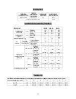
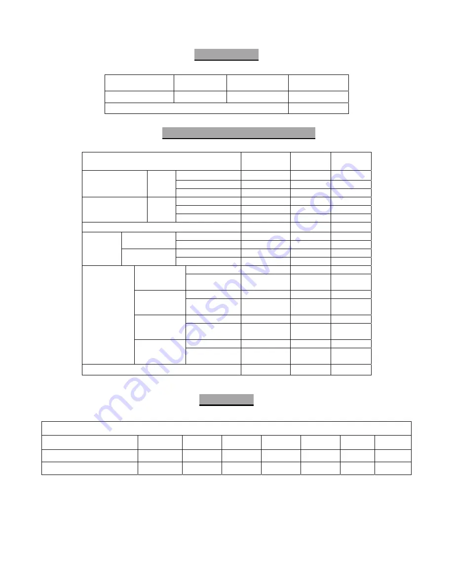
Diagram no. 2


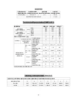
Technical specifications(Tabla 1) 


Table no. 2) 


SUPPLY 

VOLTAGE 

CABLE 

SECTION 

POWER SWITCH 

FUSE 

DIFFERENTIAL 

DEVICE 

230 V 50-60 Hz 

2 x 1.5 mm²+T 

4A 

30 mA 

ELECTRICAL OUTPUT kW 

0.1 kW 

MODEL CE6-20 

CE6-40 

CE6-41 

Width 

400 600 

600 

Depth 650 

650 

650 

EXTERNAL 

DIMENSIONS 

(mm) 

Height 290 

290 

850 

Width --- 

--- 

450 

Depth --- 

--- 

400 

OVEN 

DIMENSIONS 

(mm) 

Height --- 

--- 

300 

NET WEIGHT (kg) 

17 26 

80 

1.5 kW/h (table) 

PLATES 

2 kW/h (table) 

1 kW/h (grill) 

NO. OF 

RESISTORS 

1 kW/h (oven) 

Cable Sect. 

4 x 1.5 mm

2

+T 

4 x 2,5 mm

2

+T 

4 x 4 mm

2

+T 

380...415V 3N 

Power Switch 
Fuse 

9A 16A 

24A 

Cable Sect. 

2 x 2,5 mm

2

+T 

2x 6 mm

2

+T 

2 x 16 mm

2

+T

220...240V 1N 

Power Switch 
Fuse 

18A 33A 

59A 

Cable Sect. 

3 x 2,5 mm

2

+T 

3 x 4 mm

2

+T 

3 x 6 mm

2

+T 

220V 3 

Power Switch 
Fuse 

15A 21A 

36A 

Cable section 

3 x 1.5 mm

2

+T 

3 x 1,5mm

2

+T 

3x 4 mm

2

+T 

SUPPLY 

VOLTAGE 
(50/60 Hz) 

440V 3 

Power Switch 
Fuse 

5A 12A 

21A 

TOTAL POWER kW 

4 7.5 

13.5 

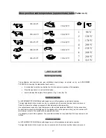
POWERS CORRESPONDING TO DIFFERENT TABLE SWITCH POSITIONS  

TABLE 

PLATES  0  6 5 4 3 2 

1,5 kW/h 

0 W 

1500 W 

1125 W 

750 W 

375 W 

250 W 

150 W 

2 kW/h 

0 W 

2000 W 

1500 W 

1000 W 

500 W 

330 W 

200 W 

Summary of Contents for CE6-20

Page 1: ...n l utilisation et l entretien FOURNEAUX ELECTRIQUES General instructions for installation use and maintenance ELECTRIC RANGES Allgemeine bedienungssanleitung f r Installation Gebrauch und Wartung ELE...

Page 2: ...M Control P Pilot E Hole for the cable to go through M Mando P Piloto E Orificio para pasar cable manguera M Control P Pilot E Hole for the cable to go through M Mando P Piloto E Orificio para pasar...

Page 3: ...2 CE6 41 M Control P Pilot C Hole for the cable to go through M Mando P Piloto C Orificio para pasar cable manguera Mth Mando termostato Horno Mrm Mando resistencias horno...

Page 4: ...3 Fig 5 Fig 2...

Page 5: ...onsejamos estudie detenidamente este manual copilado por los jefes de cocina de FAGOR nicamente as podr beneficiarse al m ximo de las m ltiples posibilidades y ventajas que le brinda este aparato Cons...

Page 6: ...kW h grill 3 N DE RESISTENCIAS 1 kW h horno 3 Secc Manguera 4x1 5mm 2 T 4x2 5mm 2 T 4x4mm 2 T 380 415V 3N Intensidad Nonimal 9A 16A 24A Secc Manguera 2x2 5mm 2 T 2x6mm 2 T 2x16mm 2 T 220 240V 1N Inten...

Page 7: ...es y temperaturas aproximadas del horno Tabla 3 220 280 C 230 250 C 250 300 C 230 250 C 220 250 C 210 240 C 200 220 C 200 230 C 220 250 C 190 210 C 1 2 3 4 5 6 7 8 90 C 120 C 170 C 200 C 230 C 260 C 2...

Page 8: ...de fusibles Es obligatorio conectar a tierra el aparato El fabricante no se hace responsable de posibles da os originados por el incumplimiento de este requisito La secci n de cable manguera y el valo...

Page 9: ...E Se recomienda no tener las placas encendidas en vac o sin carga cazuelas sartenes etc ya que se estropean 3 MANTENIMIENTO Limpieza diaria Para que el aparato se mantenga como el primer d a es conven...

Page 10: ...irmado por el s mbolo que se encuentra en el producto manual del usuario o embalaje Dependiendo de sus caracter sticas los materiales pueden reciclarse Mediante el reciclaje y otras formas de procesam...

Page 11: ...ce manuel compil par les chefs cuisiniers de FAGOR Ce n est qu ainsi qu il vous sera possible de tirer le plus grand parti des multiples possibilit s et avantages que vous offre cet appareil Conservez...

Page 12: ...3 N DE R SISTANCES 1 kW h tour 3 Sect c ble 4x1 5mm 2 T 4x2 5mm 2 T 4x4mm 2 T 380 415V 3N Fusible int General 9A 16A 24A Sect c ble 2x2 5mm 2 T 2x6mm 2 T 2x16mm 2 T 220 240V 1N Fusible int G n ral 18A...

Page 13: ...e la tension du r seau correspond celle qui est indiqu e sur la plaque signal tique Pour le branchement utiliser un c ble de conduite en polychloropr ne ou un autre mat riel ayant des caract ristiques...

Page 14: ...era nous indiquant que les r sistances fonctionnent f Lorsque le four atteint la temp rature choisie les r sistances arr tent de fonctionner par l interm diaire du thermostat et le voyant ORANGE s tei...

Page 15: ...mais il doit tre d pos dans un point de r cup ration d appareils lectriques et d quipements lectroniques afin d tre recycl Ce fait est confirm par un symbole qui se trouve sur le produit le manuel d...

Page 16: ...ou thoroughly read this manual compiled by FAGOR s kitchen supervisors in order to benefit to the maximum from the multiple possibilities and advantages this appliance offers you Keep this manual near...

Page 17: ...O OF RESISTORS 1 kW h oven 3 Cable Sect 4 x 1 5 mm 2 T 4 x 2 5 mm2 T 4 x 4 mm 2 T 380 415V 3N Power Switch Fuse 9A 16A 24A Cable Sect 2 x 2 5 mm 2 T 2x 6 mm 2 T 2 x 16 mm 2 T 220 240V 1N Power Switch...

Page 18: ...D TECHNICIAN should always carry out the appliance s electrical connection The legal standards in force in each country on connections to the mains should be taken into account Check that the mains vo...

Page 19: ...situated on the outside of the appliance f Turn the M control Fig 2 of the switch corresponding to the plate you want to turn on to the chosen position or power and then the P1 pilot light will turn...

Page 20: ...ent that can affect the safety of the appliance must be carried out by an AUTHORISED TECHNICIAN Before making any changes ensure that the power switch is off 4 ENVIRONMENTAL PROTECTION RECOMMENDATION...

Page 21: ...lltextseiten Allerdings raten wir Ihnen dazu das vorliegende von den FAGOR K chenchefs verfasste Handbuch gr ndlich durchzulesen da Sie nur so in den Genuss der vielf ltigen M glichkeiten und Vorteile...

Page 22: ...ANZAHL HEIZWIDER ST NDE 1 kW h Ofen 3 Querschnitt Schlauch 4x1 5mm 2 T 4x2 5mm 2 T 4x4mm 2 T 380 415V 3N Interne Hauptsicherung 9A 16A 24A Querschnitt Schlauch 2x2 5mm 2 T 2x6mm 2 T 2x16mm 2 T 220 24...

Page 23: ...n positionen und ungef hren temperaturen des ofens Tabelle Nr 3 220 280 C 230 250 C 250 300 C 230 250 C 220 250 C 210 240 C 200 220 C 200 230 C 220 250 C 190 210 C 1 2 3 4 5 6 7 8 90 C 120 C 170 C 200...

Page 24: ...die auf die Nichteinhaltung dieser Voraussetzung zur ckzuf hren sind Der Querschnitt des Kabelschlauchs und der Wert der am Hauptschalter zu installierenden Sicherungen gehen aus der bersicht Nr 2 he...

Page 25: ...n h Zur Reinigung des Ger tes darf kein Druckwasser verwendet werden Die inneren Oberfl chen sollten t glich nach der Benutzungs des Ofens gereinigt werden wof r Sie am besten eines der speziellen fet...

Page 26: ...et Einige der Werkstoffe k nnen wiederverwertet werden Durch Recycling und andere Formen der Weiterverwertung k nnen Sie entscheidend zum Schutz der Umwelt beitragen Wenden Sie sich an die rtlichen Be...

Page 27: ...o di studiare attentamente il presente manuale redatto dai responsabili di cucina di FAGOR in modo tale di trarre i massimi vantaggi dalle molteplici possibilit che offre il presente apparecchio Conse...

Page 28: ...RESISTENZE 1 kW h forno 3 Sezione flessibile 4x1 5mm 2 T 4x2 5mm 2 T 4x4mm 2 T 380 415V 3N Fusibile int Generale 9A 16A 24A Sezione flessibile 2x2 5mm 2 T 2x6mm 2 T 2x16mm 2 T 220 240V 1N Fusibile int...

Page 29: ...e temperature approssimative del forno Tabella n 3 220 280 C 230 250 C 250 300 C 230 250 C 220 250 C 210 240 C 200 220 C 200 230 C 220 250 C 190 210 C 1 2 3 4 5 6 7 8 90 C 120 C 170 C 200 C 230 C 260...

Page 30: ...e dei fusibili da installare nell interruttore generale indicato nel quadro No 2 MOLTO IMPORTANTE Prima di rimontare il pannello dei comandi fissare fortemente il flessibile di alimentazione elettrica...

Page 31: ...uperficie dei forni deve essere pulita giornalmente dopo essere stata utilizzata per fare ci si consiglia l uso di qualsiasi prodotto sgrassante specifico presente sul mercato Indicazioni per l uso de...

Page 32: ...tiche i materiali possono essere riciclati Grazie al riciclaggio e ad altri sistemi di smaltimento dei rifiuti elettrici ed elettronici si pu contribuire in modo significativo ad aiutare e proteggere...

Reviews: