background image

 46

E

XAMPLE


MANUAL

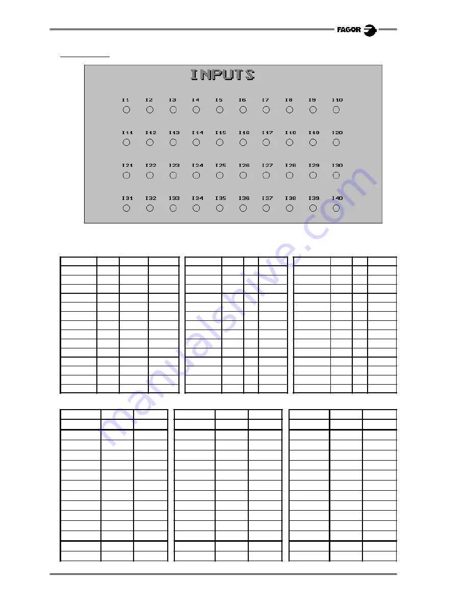
Editing page 2

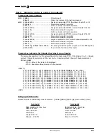
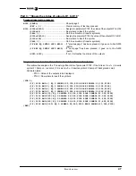
Access the screen customizing mode and select: [Utilities] [Edit] [Page] 2 [Enter]

Select background color:

Navy blue

Edit the following texts:

Edit the following circles (unfilled) with white main color and line type: Fine solid.

Main color

Size

Text

Position

Main color

Size

Text

Position

Main color

Size

Text

Position

White

Large

INPUTS

X226

Y10

White

Small

I13

X180 Y140

White

Small

I27

X380 Y210

Red

Large

INPUTS

X224

Y8

White

Small

I14

X230 Y140

White

Small

I28

X430 Y210

White

Small

I1

X80

Y70

White

Small

I15

X280 Y140

White

Small

I29

X480 Y210

White

Small

I2

X130

Y70

White

Small

I16

X330 Y140

White

Small

I30

X530 Y210

White

Small

I3

X180

Y70

White

Small

I17

X380 Y140

White

Small

I31

X80

Y280

White

Small

I4

X230

Y70

White

Small

I18

X430 Y140

White

Small

I32

X130 Y280

White

Small

I5

X280

Y70

White

Small

I19

X480 Y140

White

Small

I33

X180 Y280

White

Small

I6

X330

Y70

White

Small

I20

X530 Y140

White

Small

I34

X230 Y280

White

Small

I7

X380

Y70

White

Small

I21

X80

Y210

White

Small

I35

X280 Y280

White

Small

I8

X430

Y70

White

Small

I22

X130 Y210

White

Small

I36

X330 Y280

White

Small

I9

X480

Y70

White

Small

I23

X180 Y210

White

Small

I37

X380 Y280

White

Small

I10

X530

Y70

White

Small

I24

X230 Y210

White

Small

I38

X430 Y280

White

Small

I11

X80

Y140

White

Small

I25

X280 Y210

White

Small

I39

X480 Y280

White

Small

I12

X130 Y140

White

Small

I26

X330 Y210

White

Small

I40

X530 Y280

Main color

Center

Move to...

Main color

Center

Move to...

Main color

Center

Move to...

White

X90

Y95

X90

Y102

White

X290 Y165 X290 Y172

White

X490 Y235 X490

Y242

White

X140

Y95

X140

Y102

White

X340 Y165 X340

Y172

White

X540 Y235 X540

Y242

White

X190

Y95

X190

Y102

White

X390 Y165 X390 Y172

White

X90

Y305

X90

Y312

White

X240

Y95

X240

Y102

White

X440 Y165 X440

Y172

White

X140 Y305 X140

Y312

White

X290 Y95

X290 Y102

White

X490 Y165 X490

Y172

White

X190 Y305 X190

Y312

White

X340

Y95

X340

Y102

White

X540 Y165 X540

Y172

White

X240 Y305 X240

Y312

White

X390 Y95

X390 Y102

White

X90

Y235

X90

Y242

White

X290 Y305 X290 Y312

White

X440

Y95

X440

Y102

White

X140 Y235 X140

Y242

White

X340 Y305 X340

Y312

White

X490

Y95

X490

Y102

White

X190 Y235 X190

Y242

White

X390 Y305 X390 Y312

White

X540

Y95

X540

Y102

White

X240 Y235 X240

Y242

White

X440 Y305 X440

Y312

White

X90

Y165

X90

Y172

White

X290 Y235 X290 Y242

White

X490 Y305 X490

Y312

White

X140 Y165 X140

Y172

White

X340 Y235 X340

Y242

White

X540 Y305 X540

Y312

White

X190 Y165 X190

Y172

White

X390 Y235 X390 Y242

White

X240 Y165 X240

Y172

White

X440 Y235 X440

Y242

Summary of Contents for CNC 8055 T

Page 1: ...REF 1010 8055 T Examples manual CNC...

Page 2: ...ir own purpose could violate the rights of the owners It is possible that CNC can execute more functions than those described in its associated documentation however Fagor Automation does not guarante...

Page 3: ...epending on the material of the part and the tools used When machining one of the parts of these examples use the speeds recommended by the tool manufacturer The tool number will also be different dep...

Page 4: ...EXAMPLE MANUAL 1 TOOLS List of tools used in these examples...

Page 5: ...2 EXAMPLE MANUAL TOOL CALIBRATION Example of how to calibrate tool T2 using a part of known dimenstions diameter 60 mm length 100 mm Note The X axis operates in diameter...

Page 6: ...60 Enter The CNC shows the text Tool calibration Move the tool with the JOG keys until touching the part Press the softkey Load X axis The CNC shows the text Offset updated 4 Calibrate the tool along...

Page 7: ...4 EXAMPLE MANUAL User Notes...

Page 8: ...ramming in absolute G90 and incremental G91 coordinates 7 Programming of arcs G02 G03 Programming in radius 8 Programming of arcs G02 G03 Programming in diameters 9 Tangential entry exit G37 G38 and c...

Page 9: ...s the sequence of keys and softkeys Main menu JOG MDI G54 By program One of the following methods must be used Execute in MDI mode the following program blocks and then execute the part program Edit a...

Page 10: ...1 G0 X50 Z100 G1 X0 Z80 Point A G1 G91 X15 Z 15 Section A B Z 10 Section B C X25 Z 25 Section C D Z 30 Section D E G0 G90 X50 Z100 M30 Programming in diameters Absolute coordinates G90 G90 G95 G96 F0...

Page 11: ...B G1 Z 10 Section B C G2 X10 Z 30 I50 K0 Section C D G1 X10 Section D E G3 X10 Z 20 I 19 9 K 22 45 Section E F G1 Z 10 Section F G G0 G90 X60 Z120 M30 Programming the arc radius Absolute coordinates...

Page 12: ...A B G1 Z 10 Section B C G2 X20 Z 30 I50 K0 Section C D G1 X20 Section D E G3 X20 Z 20 I 19 9 K 22 45 Section E F G1 Z 10 Section F G G0 G90 X60 Z120 M30 Programming the arc radius Absolute coordinates...

Page 13: ...G36 R5 X60 Z50 Section C D G36 R5 X80 Section D E G36 R5 Z30 Section E F G36 R5 X100 Z20 Section F G G38 R4 Z0 Section G H and tangential exit G0 X120 G40 Z120 End tool radius compensation M30 Without...

Page 14: ...tside arc facing 16 Inside roughing on the Z axis and outside arc turning 18 Inside straight turning and outside roughing on the Z axis 20 Inside and outside roughing on the X axis 22 Inside and outsi...

Page 15: ...50 T9 D9 G0 X0 Z8 G83 X0 Z0 I45 773 B9 D4 K0 H0 C1 G0 Z150 Operation 2 Inside arc turning G95 G96 F0 2 S120 M4 T8 D8 G0 X20 Z20 G1 G41 X18 Z5 G84 X70 Z0 Q20 R 33 541 C2 L0 3 M0 3 H0 1 I 35 K0 G0 G40 Z...

Page 16: ...part zero MSG NEW FIXTURE REVERSE PART M0 M5 MSG ORGX54 0 ORGZ54 110 G54 G92 S2200 Operation 4 Taper turning and facing G95 G96 F0 2 S180 M4 G0 X90 Z20 G1 G42 X84 Z5 G81 X10 Z0 Q78 R 75 C2 L0 3 M0 3...

Page 17: ...9 D9 G0 X0 Z8 G83 X0 Z0 I38 773 B3 D7 K0 H0 C4 G0 Z150 Operation 2 Facing and outside turning G95 G96 F0 2 S180 M4 T2 D2 G0 X90 Z20 G1 X85 Z0 G1 X18 G1 Z5 G0 G42 X72 Z1 G1 X78 Z 2 Z 40 X85 G0 Z150 Ope...

Page 18: ...part zero MSG NEW FIXTURE REVERSE PART M0 M5 MSG ORGX54 0 ORGZ54 65 G54 G92 S2200 Operation 4 Outside taper facing G95 G96 F0 2 S180 M4 T2 D2 G0 X90 Z20 G1 G41 X83 Z5 G82 X78 Z 33 Q10 R0 C2 L0 3 M0 3...

Page 19: ...F0 15 S600 M4 Z150 T9 D9 G0 X0 Z8 G83 X0 Z0 I40 773 B3 D7 K10 H0 C4 G0 Z150 Operation 2 Inside taper facing G95 G96 F0 2 S100 M4 T8 D8 G0 X20 Z20 G1 G42 X18 Z5 G82 X20 Z 21 732 Q70 R0 C2 L0 2 M0 2 F0...

Page 20: ...MSG NEW FIXTURE REVERSE PART M0 M5 MSG ORGX54 0 ORGZ54 80 G54 G92 S2200 Operation 4 Outside arc facing G95 G96 F0 2 S180 M4 T2 D2 G0 X90 Z20 G41 X84 Z5 G85 X78 Z 27 Q10 R0 C1 5 L0 3 M0 3 H0 1 I 45 01...

Page 21: ...on 1 Drilling G94 G97 F90 S600 T9 M4 Z150 T9 D9 G0 X0 Z8 G83 X0 Z0 I35 773 B5 D5 K15 H0 C1 5 G0 Z150 Operation 2 Inside profile facing G95 G96 F0 2 S100 M4 T8 D8 G0 X20 Z20 G1 X16 Z5 G69 X20 Z 25 C1 5...

Page 22: ...5 G0 Z0 G1 X66 G1 Z5 G1 G42 X72 Z1 G1 X80 Z 3 G0 G40 Z150 Second fixture Set new part zero MSG NEW FIXTURE REVERSE PART M0 M5 MSG ORGX54 0 ORGZ54 80 G54 G92 S2200 Operation 4 Outside arc turning G95 G...

Page 23: ...ning G95 G96 F0 2 S180 M4 G0 Z150 T2 D2 G0 X90 Z20 G1 X85 Z0 G1 X 0 4 Z5 G0 X78 Z2 G1 Z 60 X85 G0 G41 X80 Z 4 G1 X70 Z1 G0 Z150 Operation 2 Drilling G94 G97 F90 S600 M4 T9 D9 G0 X0 Z5 G83 X0 Z0 I70 77...

Page 24: ...RT M0 M5 MSG ORGX54 0 ORGZ54 117 G54 G92 S2200 Operation 4 Outside profile facing G95 G96 F0 2 S180 M4 T2 D2 G0 X90 Z20 G1 X85 Z5 G69 X78 Z 61 403 C1 L0 3 H0 1 S100 E110 GOTO N120 N100 G1 G5 X60 Z 47...

Page 25: ...54 112 G54 G92 S2200 Operation 1 Drilling G94 G97 F90 S600 M4 G0 Z150 T9 D9 G0 X0 Z10 G83 X0 Z0 I75 773 B8 D2 K50 H0 C5 G0 Z150 Operation 2 Facing and outside turning G95 G96 F0 2 S180 M4 T2 D2 G0 X78...

Page 26: ...985 K1 293 N110 G3 X20 Z 60 R36 G1 X18 G1 Z5 G0 G40 G7 Z150 Second fixture Set new part zero MSG NEW FIXTURE REVERSE PART M0 M5 MSG ORGX54 0 ORGZ54 110 G54 G92 S2200 Operation 4 Outside profile turnin...

Page 27: ...Z150 T9 D9 G0 X0 Z5 G83 X0 Z0 I75 773 B5 D5 K130 H0 C2 G0 Z150 Operation 2 Facing and outside turning G95 G96 F0 2 S180 M4 T2 D2 G0 X78 Z5 G1 Z 50 X86 G0 G41 X79 Z 2 5 G1 X74 Z0 X16 G0 G40 Z150 Opera...

Page 28: ...zero MSG NEW FIXTURE REVERSE PART M0 M5 MSG ORGX54 0 ORGZ54 120 G54 G92 S2200 Operation 5 Outside taper threading G95 G96 F0 2 S180 M4 T2 D2 G0 X90 Z20 G1 G42 X85 Z5 G81 X17 396 Z0 Q78 R 75 C2 L0 3 M...

Page 29: ...ORGZ54 102 G54 G92 S2200 Operation 1 Facing and outside turning G95 G96 F0 2 S180 M4 G0 Z150 T2 D2 G0 X90 Z20 G1 X78 Z5 Z 38 X82 G0 Z0 G1 X 0 4 G1 Z5 G0 G42 X72 Z1 G1 X80 Z 3 X85 G0 G40 X60 Z150 Opera...

Page 30: ...G92 S2200 Operation 4 Outside profile turning G95 G96 F0 2 S180 M4 T2 D2 G0 X90 Z20 G1 X82 Z0 G1 X 0 4 G1 Z5 G0 X82 5 Z4 G68 X27 Z0 5 C1 L0 3 H0 S120 E130 G1 G42 X27 Z0 5 N120 G1 G5 X32 Z 2 X32 Z 20...

Page 31: ...ning G95 G96 F0 2 S180 M4 G0 Z150 T2 D2 G0 X90 Z20 G1 X78 Z5 G1 Z 36 F200 G1 X85 G0 Z0 G1 X 0 4 G1 Z5 G0 G42 X70 Z1 G1 X80 Z 4 G0 G40 X90 Z150 Operation 2 Drilling G94 G97 F90 S600 M4 T9 D9 G0 X0 Z10...

Page 32: ...Second fixture Set new part zero MSG NEW FIXTURE REVERSE PART M0 M5 MSG ORGX54 0 ORGZ54 128 G54 G92 S2200 Operation 6 Outside profile roughing G95 G96 F0 2 S120 M4 T2 D2 G0 X85 Z5 G68 X0 Z0 C1 5 L0 5...

Page 33: ...tside turning G95 G96 F0 2 S180 M4 G0 Z150 T2 D2 G0 X90 Z20 G1 X85 Z0 X 0 4 Z5 G1 G42 X0 Z0 G36 R5 X78 Z0 Z 35 X85 G0 G40 X90 Z150 Second fixture Set new part zero MSG NEW FIXTURE REVERSE PART M0 M5 M...

Page 34: ...G3 X40 Z 32 R92 74 G1 Z 42 G36 R5 X65 Z 49 39 X40 Z 57 N110 G2 X78 Z 90 R31 N120 G0 Z150 Operation 3 Drilling G94 G97 F90 S600 T9 M4 G0 X0 Z10 G83 X0 Z0 I35 773 B10 D2 H5 C2 G0 Z150 Operation 4 Inside...

Page 35: ...32 EXAMPLE MANUAL User Notes...

Page 36: ...33 Programming examples C axis programming 8055T Machining a profile in the ZC plane 34 Machining a profile in the XC plane 35...

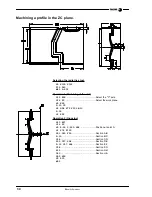
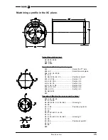
Page 37: ...36 Select the C axis G16 ZC Select the work plane G0 X90 Z 15 C0 G1 G94 X72 F100 M13 Z 35 G1 X90 Operation 2 Grooving G15 R37 G16 ZC G0 Z 50 C 125 664 Position at point A G1 X74 F100 G91 C40 F50 Secti...

Page 38: ...Position at point 1 X19 63 C34 Section 1 2 X 19 63 C34 Section 2 3 X 39 26 C0 Section 3 4 X 19 36 C 34 Section 4 5 X19 63 C 34 Section 5 6 X39 26 C0 Section 6 1 G0 G40 X50 Z10 Operation 2 Making the...

Page 39: ...36 EXAMPLE MANUAL User Notes...

Page 40: ...37 Programming examples Profile Editor 8055T Profile editor Example 1 38 Profile editor Example 2 39 Profile editor Example 3 40 Profile editor Example 4 41...

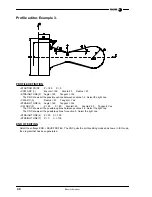
Page 41: ...NGS CHAMFER TANGENTIAL ENTRY AND EXIT Select the MODIFY option and define TANGENTIAL ENTRY Select point 1 Press ENTER Enter Radius 5 CHAMFER Select point 2 Press ENTER Enter Size 10 ROUNDING Select po...

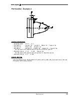
Page 42: ...enter 190 Radius 30 Tangent Yes The CNC shows all the possible options for section 2 Select the right one STRAIGHT LINE 4 Z 20 X 220 Tangent Yes The CNC shows all the possible options for sections 3 4...

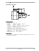
Page 43: ...20 Tangent Yes STRAIGHT LINE 4 Angle 160 Tangent Yes CW ARC 5 Z 30 X 80 Zcenter 45 Xcenter 80 Tangent Yes The CNC shows all the possible options between sections 4 5 Select the right one The CNC show...

Page 44: ...s for section 2 Select the right one CW ARC 4 Radius 10 Tangent Yes STRAIGHT LINE 5 X 40 Angle 180 Tangent Yes The CNC shows all the possible options for section 4 Select the right one CW ARC 6 Z 54 X...

Page 45: ...42 EXAMPLE MANUAL User Notes...

Page 46: ...43 Programming examples User screen customizing programs 8055T Machine diagnosis 44 Machining a pulley 52...

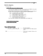
Page 47: ...ts the access code password Part 2 It shows the status of inputs I1 to I40 it uses user page 2 and the symbols 21 and 22 Part 3 It shows the status of outputs O1 to O18 It uses user page 3 and the sym...

Page 48: ...f parameter P100 If the bit is set to 1 it inserts symbol 21 lamp lit red color and if it is set to 0 it inserts symbol 22 lamp off background color Call parameters P100 Value of the inputs to be disp...

Page 49: ...te Small I37 X380 Y280 White Small I10 X530 Y70 White Small I24 X230 Y210 White Small I38 X430 Y280 White Small I11 X80 Y140 White Small I25 X280 Y210 White Small I39 X480 Y280 White Small I12 X130 Y1...

Page 50: ...routine that indicates the status of a row of outputs This subroutine analyzes the 10 least significant bits of parameter P100 If the bit is set to 1 it inserts symbol 21 lamp on red color if it is se...

Page 51: ...70 White Small O9 X505 Y70 White Small O16 X405 Y140 White Small O3 X205 Y70 White Small O10 X105 Y140 White Small O17 X455 Y140 White Small O4 X255 Y70 White Small O11 X155 Y140 White Small O18 X505...

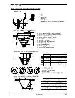
Page 52: ...rom to From to SYMBOL 0 X0 Y0 X400 Y30 X100 Y0 X100 Y30 X200 Y0 X200 Y30 X300 Y0 X300 Y30 SYMBOL 1 X0 Y0 X20 Y30 X20 Y0 X400 Y30 X100 Y0 X100 Y30 X200 Y0 X200 Y30 X300 Y0 X300 Y30 SYMBOL 2 X0 Y0 X40 Y...

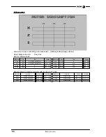
Page 53: ...X120 Y10 White Large S X80 Y253 Red Large MOTOR CONSUMPTION X118 Y8 White Small 25 X220 Y80 White Large X X80 Y113 White Small 50 X320 Y80 White Large Z X80 Y183 White Small 75 X420 Y80 Main color Ele...

Page 54: ...E SYMBOL 21 480 P199 IF P100 AND 200 EQ 0 SYMBOL 22 530 P199 ELSE SYMBOL 21 530 P199 RET Part 3 status of the outputs N300 PAGE3 KEY 0 N310 P100 PLCO1 P199 85 CALL 3 P100 PLCO10 P199 155 CALL 3 IF KEY...

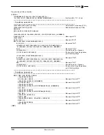
Page 55: ...e a user screen customizing program In order to be able to execute this program in the user channel of the Editing mode general machine parameter USEREDIT must be set with the program number Once all...

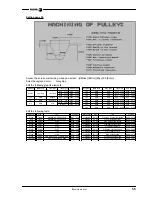
Page 56: ...lley P103 Depth of the groove in radius P104 Width of the groove P105 Safety distance P106 Maximum machining depth P107 Finishing stock P108 Cutting feedrate P109 Roughing feedrate in mm rev P110 Fini...

Page 57: ...Nr of passes IF P115 LE 0 GOTO N100 If done with all roughing passes go to finishing stage P1 2 P106 P2 P106 TAN P100 2 X P1 ZP2 Movement D E P2 P104 2 P107 COS P100 2 2 P103 P107 TAN P100 2 2 PPOSX...

Page 58: ...ite Solid X100 Y120 X220 Y120 Line White Solid X35 Y165 X35 Y120 Main color Size Text Position Main color Size Text Position White Large MACHINING OF PULLEYS X87 Y10 Light blue Small P101 Abs Z center...

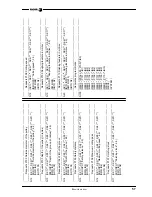
Page 59: ...12 If P102 go on to N12 IF KEY EQ FC03 GOTO N13 If P103 go on to N13 IF KEY EQ FC04 GOTO N14 If P104 go on to N14 IF KEY EQ FC05 GOTO N15 If P105 go on to N15 IF KEY EQ FC06 GOTO N2 If option go on to...

Page 60: ...SK3 SK4 SK5 SK6 SK7 IB6 INPUT Maximum cutting pass 6 5 DW6 IB6 GOTO N2 Requests P107 Finishing stock N17 SK1 SK2 SK3 SK4 SK5 SK6 SK7 IB7 INPUT Finishing stock 6 5 DW7 IB7 GOTO N2 Requests P108 Cutting...

Reviews: