background image

Screen and keys

6

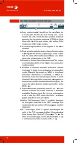
General description of the interface.

A. Icon (customizable) identifying the manufacturer.

Clicking with the mouse or pressing on a touch-
screen, the CNC shows the task window (same as
pressing the keystroke sequence [CTRL]+[A]) that
shows the list of the work modes, user modes, OEM
modes and CNC hotkey modes.

B. Icon showing the status of the program of the active

channel:

C. Program selected in the active channel for execution.

Clicking with the mouse or pressing a touch-screen
has the same effect as the [Main-Menu] key, which
shows the initial screen of the CNC.

D. Number of the last Nxxxx label executed. The bottom

icon indicates whether the Single-block execution
mode is active.

E. Number of channels available and active channel

(indicated in blue). Icons indicate which execution
mode (Manual, Automatic or MDI), or simulated
execution (theoretical, G functions, G S M and T
functions, fast and fast [S=0]) is found in each
channel. Clicking with the mouse or pressing a touch-
screen to access the desired channel, doing it on the
icon of the active channel, has the same effect as the
[ESC] key.

F. Active work mode (automatic, manual, etc.) selected

screen number and total number of screens
available. System clock. By clicking on the active
work mode, the CNC shows the list of available
pages and which ones are visible.

G. Active CNC message. If the "+" symbol is displayed

on the right hand side of the CNC message, this
means that there are other CNC messages on other
channels.

H. PLC messages. If the "+" symbol appearing on the

right of the PLC message is blue, this means that
there is more than 1 active PLC message. To see the
other active messages, click it with the mouse or tap
it on the touch-screen or press [CTRL + M].

A

B

C

D

E

F

G

H

Summary of Contents for CNC 8060

Page 1: ...CNC 8060 65 User quick reference Ref 1906...

Page 2: ...not guarantee the validity of those applications Therefore except under the express permission from Fagor Automation any CNC application that is not described in the documentation must be considered a...

Page 3: ...O language 45 ISO Canned cycles M 65 ISO canned cycles T 83 Conversational mode 103 Conversational cycles M 119 Conversational cycles T 129 Measuring and calibration cycles M 137 Measuring and calibra...

Page 4: ...ated for versionsuptoV05 7x V01 7x Simulator The CNC simulator provides the user with a complete tool to create optimize and check programs directly at the PC He can then transfer them directly on the...

Page 5: ...5 Screen description General screen description A General CNC status bar B Screen for the active work mode C Vertical softkey menu D Horizontal softkey menu A B C D SCREEN AND KEYS...

Page 6: ...e Icons indicate which execution mode Manual Automatic or MDI or simulated execution theoretical G functions G S M and T functions fast and fast S 0 is found in each channel Clickingwiththemouseorpres...

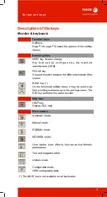
Page 7: ...een the different windows of the screen BACK key On the horizontal softkey menu it may be used to go from a softkey submenu up to the previous menu The ESC key performs the same function Help key HELP...

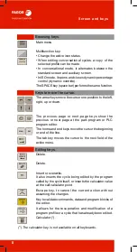
Page 8: ...t right up or down The previous page or next page keys show the previous or next page at the part program or PLC program editor The home and end keys move the cursor the beginning or end of the line T...

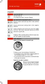
Page 9: ...apidkey Whenpressingthis keywhilemovinganaxis the CNC applies the rapid feedrate Feed selectors Selector of the manual movement type Continuous jog incremental jog or handwheel In handwheel mode it se...

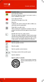
Page 10: ...the end of each block Machine reference zero home search This key only works in MANUAL mode It can be used directly where it calls the home search subroutine for all axes or it can be used after selec...

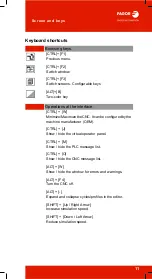
Page 11: ...imizetheCNC It canbe configuredbythe machine manufacturer OEM CTRL J Show hide the virtual operator panel CTRL M Show hide the PLC message list CTRL O Show hide the CNC message list ALT W Show hide th...

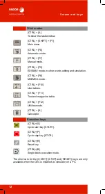
Page 12: ...ndow CTRL SHIFT F1 Main menu CTRL F6 Automatic mode CTRL F7 Manual mode CTRL F9 EDISIMU mode in other words editing and simulation CTRL F8 MDI MDA mode CTRL F10 User tables CTRL F11 Tool and magazine...

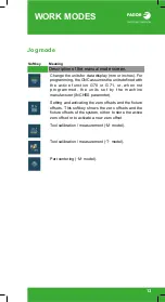
Page 13: ...or when not programmed the units set by the machine manufacturer INCHES parameter Setting and activating the zero offsets and the fixture offsets This softkey shows the zero offsets and the fixture of...

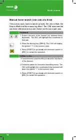
Page 14: ...ght the coordinate of that axis 2 Press the homing key ZERO The CNC will display the symbol 1 in the numeric area 3 Press START to go ahead with the home search or ESC to cancel the operation Softkey...

Page 15: ...symbol 1 in the numeric area 2 Press START to go ahead with the home search or ESC to cancel the operation Softkey menu 1 Press the home search softkey to show the list of axes of the channel 2 Select...

Page 16: ...eyboard is acted upon 1 Turn the jog selector switch to the continuous JOG position 2 In incremental mode it selects the incremental value of the axis movements Movement in incremental jog In incremen...

Page 17: ...selected the CNC will move itasthehandwheelisturneddependingonthesetting of the selector switch and on the turning direction of the handwheel Individual handwheel it is associated with a particular ax...

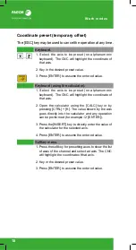
Page 18: ...ll highlight the coordinate of that axis 2 Open the calculator using the CALC key or by pressing CTRL K The value shown by the axis goes directly into the calculator and any operation can be performed...

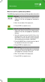
Page 19: ...C will highlight the coordinate of that axis 2 Open the calculator using the CALC key or by pressing CTRL K The value shown by the axis goes directly into the calculator and any operation can be perfo...

Page 20: ...electing the desired spindle When pressing this key for the first time the CNC will highlight the relevant data indicating that it is selected 2 Enter the new spindle speed 3 Press START to assume the...

Page 21: ...the spindle same as M05 function Orient the spindle same as M19 function Keyboard JOG keypad Increases or decreases the percentage of spindle speed The maximum and minimum values as well as the incre...

Page 22: ...no probe a reference part is required to calibrate the tool All the movements are carried out manually Semi automatic calibration with a probe The positioning movements are carried out manually and t...

Page 23: ...the model trihedron Calibrate the length or offsets of the endmills and the offsets of the lathe tools Tool calibration steps 1 Define the dimensions of the reference part being used in the calibratio...

Page 24: ...nge if ENTER is pressed the CNC will only show the tool data 3 Manually approach the tool to the probe until it is placed on the path that will be used for probing To calibrate the radius with a cylin...

Page 25: ...del plane Calibrate the offset of any tool Lathe model trihedron Calibrate the length the radius or offsets of the endmills and the offsets of the lathe tools Tool calibration steps 1 Select the tool...

Page 26: ...ell as in rectangular parts the inclination of the part with respect to the abscissa axis The type of part to be centered is selected with the parameters of the cycle Type of part to be centered Recta...

Page 27: ...y it into the edit line Execute blocks The START key executes the block currently displayed on the editing line Once the block has been executed is saved in the block history The START key also direct...

Page 28: ...f the softkeys of the automatic mode Select a program for execution Begin tool inspection Tool inspection is only available when program execution is interrupted End simulated execution and start exec...

Page 29: ...herwise the program execution will begin from the first block of the program to the execution of one of the end of program functions M02 or M30 As an option it is possible to define the first and last...

Page 30: ...ution from that point on Depending on the type of simulation selected it can involve movement of axes spindle etc These can cause collisions depending on the type of machine Path Axis movement Spindle...

Page 31: ...utionmode afterpressing the softkey the CNC goes into tool inspection to reposition the axes modify program conditions etc To complete the tool inspection and before starting the execution of the prog...

Page 32: ...the program or of the subroutine set by the operator Executing block search 1 Selecting the type of search automatic or manual 2 Selecting the stop block In the automatic block search there is no need...

Page 33: ...he repositioning end point and the corresponding software limit Automatic repositioning of axes Select the axes with the relevant softkey and press START Repositioning may be interrupted using the STO...

Page 34: ...G and M functions feedrate spindle speed tool and other commands that were programmed However the CNC treats certain functions and commands type of movements radius compensation etc differently Refer...

Page 35: ...nction to restore The spindle turning status may be restored either together with the repositioning of the axes or separately If the spindle was interrupted in a positioning with M19 repositioning wil...

Page 36: ...hannel being displayed for editing and simulation It does not affect the active channel at the CNC This icon will only be availablewhen theCNC has channels Select the single block or continuous execut...

Page 37: ...gram If it is a new program it will be saved in this folder 2 Select the program from the list or write its name in the bottom window To edit a new program write the name of the program in the lower w...

Page 38: ...s after executing one of the end of program functions M02 or M30 As an option it is possible to define the first and last blocks of the simulation To simulate the program the CNC assumes the real conf...

Page 39: ...the active origins for execution When starting the simulation or pressing the simulation reset the CNC applies to the simulation the origins set in the execution environment for example the part zero...

Page 40: ...a value in the table Accessing the tables of other channels With some tables only the data of the active channel are displayed this softkey is used to show the tables of the other channels This softk...

Page 41: ...cuting the command G158 Absolute zero offsets besides being set directly in the table may also be set from the PLC or via part program using variables The zero offsets are used to place the part zero...

Page 42: ...Global parameters There is a table for each channel Local parameters There are seven tables for each channel one table per nesting level 7 levels The parameter values may be set directly in the table...

Page 43: ...les The attributes column shows the letter M indicating that the program may be modified This attribute is used to protect the files so they can t be modified from the EDISIMU mode Change the hidden a...

Page 44: ...Work modes 44...

Page 45: ...N Number type block label 0 4294967295 G Preparatory functions 1 999 X Y Z A B C U V W Position of the axes If XvalueI or Xn valueI the programmed position is incremental 99999 9999 mm 9999 99999 inc...

Page 46: ...same block The programmed speed stays active until another value is programmed The programming units will be rpm unless selected otherwise If G96 is active the programming units will be m min T Tool...

Page 47: ...ndles Sn n 1 to 9 M41 Sn M44 Sn Function Meaning M00 Program stop M01 Conditional program stop M02 M30 End of program M03 Start the spindle clockwise 1 M04 Start the spindle counterclockwise 1 M05 Sto...

Page 48: ...fault quality of the function depends on the settings of the CNC machine parameters V This function is displayed in the G code history Function M D V Meaning G00 Rapid positioning G00 X I Y I Z I R I...

Page 49: ...G06 or after activating function G261 G03 Counterclockwise circular helical interpolation See G06 G261 G262 G03 X I Y I I J Z G17 G03 X I Z I I K Y G18 G03 Y I Z I J K X G19 G03 X I Y I R X Y Z coordi...

Page 50: ...dinates of the end point of the arc R Q polar coordinates of the final point of the arc I J coordinates of the intermediate point of the arc for both cartesian points and polar points G10 Cancel mirro...

Page 51: ...ond ordinate and third axis perpendicular of the channel G17 G18 Main plane formed by the third axis abscissa first axis ordinate and second axis perpendicular of the channel G18 G19 Main plane formed...

Page 52: ...pectively for abscissa ordinates and perpendicular plane Q1 Spindle angular position for the starting point of the thread default Q1 0 G36 Automatic radius blend G36 I I value of the rounding radius i...

Page 53: ...The angle is defined in degrees 359 9999 G50 Semi rounded corner G50 G53 Cancel zero offset See MCS G53 G54 Zero offset See G159 G54 absolute zero offset 1 G55 Zero offset G55 absolute zero offset 2...

Page 54: ...ing factor Note it is annulled by only programming G72 G73 Rotation of the coordinate system G73 Q I J Q rotation angle incremental I J abscissa and ordinate of the rotational center optional Note it...

Page 55: ...may be 0 or another value G93 Feedrate in seconds block G93 F F time in seconds for the programmed movement G94 Feedrate in millimeters minute inches minute G94 F F feedrate in millimeters minute or i...

Page 56: ...e theoretical position value is not included in the resulting offset of the measurement G103 Probing until not making contact G103 Axis1 axis2 Axis n F axis1 Axis n position value of probing point F m...

Page 57: ...cceleration to be applied global See SLOPE G131 acceleration percentage to be applied for all axes and spindle Example G131 100 all axes and spindles at 100 of the selected acceleration G132 Percentag...

Page 58: ...ed per axis maximum 120 Example G135 X50 Y75 Z110 X AC forward at 50 Y at 75 and Z at 110 G136 Circular transition between blocks G136 G137 Linear transition between blocks G137 G138 Direct activation...

Page 59: ...applicable Example G157 Y G55 the second zero offset is applicable except on the Y axis which retains the previous movement G158 Zero offset Incremental zero offset G158 X Y Z A B C U V W X W value of...

Page 60: ...nes See G380 G399 G180 G189 P0 P1 P99 G180 G189 A B Z P0 Pn local parameters of the subroutine optional Example G183 P1 12 3 P2 6 Note these are functions that the manufacturer can use for its specifi...

Page 61: ...e at the cutting point increases on inside arcs and decreases on outside arcs G198 Set lower software travel limits G198 X W X W lower software limit for the movement of the axes G199 Set upper softwa...

Page 62: ...enter referred to starting point See G06 G261 G262 Note when this function is active the CNC interprets that the coordinates of the arc center are referred to the starting point of the arc G263 Arc ra...

Page 63: ...al parameters of the subroutine optional Example G388 A12 3 B45 3 P10 6 Note these are functions that the manufacturer can use for its specific functions it is possible that they are not present G500...

Page 64: ...ISO language 64...

Page 65: ...D M G99 G1 G81 X60 Y0 Z2 I 20 F1000 S2000 M4 G99 G1 X60 Y0 F1000 S2000 M4 G81 Z2 I 2 Function M D V Meaning G80 Cancel the canned cycle G80 G81 Drilling canned cycle G81 Z I K A Z Reference plane I Dr...

Page 66: ...feedrate withdrawal G0 J0 it returns to the coordinate value H after each step J1 it returns to the coordinate value Z J 1 after each step it returns the distance indicated by H and every J step to t...

Page 67: ...lling canned cycle with constant peck G83 Z I J B K Z Reference plane I Drilling peck step J Number of drilling pecks B Rapid withdraw G0 distance after each drilling step K Dwell in seconds at the bo...

Page 68: ...ate factor When rigid tapping the returning feedrate will be J times the tapping feedrate When not programmed or programmed J1 they will both be the same B Penetration step when tapping with chip remo...

Page 69: ...ISO canned cycles M 69 G85 Reaming canned cycle G85 Z I K Z Reference plane I Reaming depth K Dwell in seconds at the bottom of the hole default 0 Function M D V Meaning...

Page 70: ...d A1 The tool goes into the hole stopped and comes out turning When not programmed the tool goes into the hole and comes out turning When programming A0 or A1 define the spindle stop with parameters Q...

Page 71: ...kwise K Half width of the pocket M Corner type 0 square 1 rounded 2 chamfered default value 0 Q Rounding radius or chamfer size B Depth of pass C Milling pass or width If not programmed or programmed...

Page 72: ...e the same if B 0 the pocket is machined with the set step except the last step that machines the rest C Milling pass or width If not programmed or programmed with a 0 value it assumes a value of 3 4...

Page 73: ...ISO canned cycles M 73 G99 Withdrawal to the reference plane at the end of the canned cycle G99 Note use G98 to avoid obstacles fixtures Function M D V Meaning...

Page 74: ...0 I Machining depth It may be programmed either in absolute or incremental coordinates in which case it will be referred to the reference plane J Hole diameter K Pre drilling diameter B Profiles Note...

Page 75: ...reference plane J Thread diameter K Thread depth B Thread pitch C Type of threading When programming C 0 the threading will be done in a single pass When programming C 1 it will make one thread per ea...

Page 76: ...of the thread pitch is from the surface of the part to the bottom B 0 the direction of the thread pitch is from the bottom to the surface of the part C Type of threading When programming C 0 the threa...

Page 77: ...re not programmed the CNC understands that it mustperformmachiningatallthepointsalongtheprogrammed path Function M D V Meaning G160 Multiple machining in a straight line G160 A X I K P Q R S T U V A A...

Page 78: ...s along the path K Total number of machining operations along the path including that of the machining definition point Y Width of the parallelogram J Step between machining operations along the path...

Page 79: ...long the path K Total number of machining operations along the path including that of the machining definition point Y Width of the grid J Step between machining operations along the path D Total numb...

Page 80: ...ign indicates the direction I counterclockwise and I clockwise K Total number of machining operations including that of the machining definition point C Type of movement between machining points defau...

Page 81: ...e in G00 or G01 the sign indicates the direction I counterclockwise and I clockwise K Total number of machining operations including that of the machining definition point C Type of movement between m...

Page 82: ...is done in G00 or G01 the sign indicates the direction I counterclockwise and I clockwise K Total number of machining operations including that of the machining definition point C Type of movement bet...

Page 83: ...C Machining pass in radius A Machining main axis A 0 main axis Z A 1 main axis X L Finishing stock on the X axis in radius M Finishing stock on the Z axis If not programmed it will be that indicated f...

Page 84: ...travel in each section on the machining axis K Penetration feedrate in the roots F Feedrate for the last roughing pass If not programmed or programmed as F0 it does not run the last roughing pass H Fi...

Page 85: ...ted for parameter L K Penetration feedrate in the roots F Feedrate for the last roughing pass If not programmed or programmed as F0 it does not run the last roughing pass H Finishing feedrate If not p...

Page 86: ...the same as the entry path D 0 retracts at 45 degrees D not programmed retracts while following the profile to the previous step L Finishing stock on the X axis in radius M Defines the finishing pass...

Page 87: ...the same as the entry path D 0 retracts at 45 degrees D not programmed retracts while following the profile to the previous step L Finishing stock on the X axis in radius M Defines the finishing pass...

Page 88: ...depth B Type of machining B 0 tapping B 0 drilling where B indicates the drilling peck D Safety distance K Dwell at the bottom of the hole in hundredths of a second H Rapid withdrawal G0 distance aft...

Page 89: ...ed retracts while following the profile to the previous step L Finishing stock on the X axis in radius M Defines the finishing pass along the Z axis if not programmed a value of 0 will be assumed F Fe...

Page 90: ...ed retracts while following the profile to the previous step L Finishing stock on the X axis in radius M Defines the finishing pass along the Z axis if not programmed a value of 0 will be assumed F Fe...

Page 91: ...he penetration pass can reach when B 0 D X axis safety distance in radius L Finishing stock in radius C Thread pitch C 0 Pitch according to the taper C 0 Pitch according to the associated axis J Exit...

Page 92: ...he initial side or right H 3 Entry from final flank to the left H 4 Entry in radial zigzag from the final center beginning from the final side or left H 5 Entry in zigzag from the flanks alternating t...

Page 93: ...nt B 0 Decreasing pitch increment E Minimum value that the penetration pass can reach when B 0 D Safety distance along Z L Finishing stock C Thread pitch C 0 Pitch according to the taper C 0 Pitch acc...

Page 94: ...beginning from the initial side or right H 3 Entry from final flank to the left H 4 Entry in radial zigzag from the final center beginning from the final side or left H 5 Entry in zigzag from the fla...

Page 95: ...X coordinate of the groove s starting point Z Z coordinate of the groove s starting point Q X coordinate of the groove s end point R Z coordinate of the groove s end point C Grooving pass D X axis sa...

Page 96: ...starting point Z Z coordinate of the groove s starting point Q X coordinate of the groove s end point R Z coordinate of the groove s end point C Grooving pass in radius D Safety distance along Z K Dw...

Page 97: ...on A Angular increment between machining operations J Total number of machining operations D Safety distance along Z K Dwell at the bottom of the hole in hundredths of a second H Rapid withdrawal G0 d...

Page 98: ...on A Angular increment between machining operations J Total number of machining operations D Safety distance along X K Dwell at the bottom of the hole in hundredths of a second H Rapid withdrawal G0 d...

Page 99: ...d to the starting point I Depth of the slot referred to the starting point Q Angular position of the spindle for the first machining operation A Angular increment between machining operations J Total...

Page 100: ...ed to the starting point I Depth of the slot referred to the starting point Q Angular position of the spindle for the first machining operation A Angular increment between machining operations J Total...

Page 101: ...the part profile is known it is recommended to define both profiles that of the rough part and the desired final profile The machining is faster since only the stock between both profiles is removed B...

Page 102: ...ISO canned cycles T 102...

Page 103: ...ication lines etc MC TC conversational mode Intuitive operation and programming of the machine Allows for cycles to be programmed without using the ISO language Programming in conversational mode isba...

Page 104: ...ional mode Accessing the conversational mode Once the CNC has been started up press the SHIFT ESC keys to switch to conversational mode Press SHIFT ESC again to return to basic mode Basic M T mode MC...

Page 105: ...versational mode screens The conversational mode has two screens where the information is displayed Standard screen Auxiliary screen To switch from one screen to another press the two color key Standa...

Page 106: ...on on the spindle 9 Softkeys for cycle editing 10 Message bar 11 Real spindle rpm 12 Position coordinates of the axes The symbol indicates that the axis is working in diameters If there are more than...

Page 107: ...high level command has been programmed such as FIX KIN CS 7 Window that displays information on the selected tool 8 Window that displays information on the feedrate of the axis that is selected 9 Wind...

Page 108: ...same family as the one selected press the softkey again to drop the menu with the available cycles Once the cycle to be edited has been selected enter the data in the windows corresponding to each on...

Page 109: ...een 1 Name of the cycle 2 Image showing the cycle parameters 3 Current parameters for the CNC position tool corrector 4 Geometric parameters 5 Roughing parameters 6 Finishing parameters 7 Description...

Page 110: ...de 110 Simulation execution and saving of a cycle Simulation execution and saving of a cycle After editing a cycle it may be simulated executed or saved using the vertical softkey menu 1 2 3 4 5 Simul...

Page 111: ...Softkey to start cycle simulation 2 Softkey to stop cycle simulation 3 Softkey to reset the simulation 4 Softkey to simulate the cycle block by block 5 The horizontalsoftkeys may be used to configureh...

Page 112: ...diting a cycle it can be executed by pressing the vertical softkey Execute cycle Following an icon with the start symbol will appear This symbol lets the user know that the cycle can be executed To ex...

Page 113: ...edited cycle To insert a cycle move the cursor and the cycle will be inserted below it 6 Window that shows the cycles and ISO coded blocks that make up the selected part To edit a cycle press RECALL...

Page 114: ...the left column the program to be simulated or executed Press the vertical softkey Graphic simulation or Execute program To toggle the focus between the list of programs and the part editor press CTR...

Page 115: ...ormation of the zero offset tables and fixture offset tables and any change made in jog mode also affects those tables Loading a new zero offset or fixture offset into the table With an active offset...

Page 116: ...ls the possibility to calibratelathetoolsandmillingtools TheCNCwillshow the necessary data and will update the help graphics according to the selected tool There are several ways to calibrate a tool S...

Page 117: ...help graphics according to the selected tool A Machine data Position of the axes tool and active tool offset real spindle speed and real feedrate of the axes B Area to define the calibration data C D...

Page 118: ...s of the milling tools On a lathe model it may be used to calibrate the offsets of any tool A Machine data Position of the axes tool and active tool offset real spindle speed and real feedrate of the...

Page 119: ...ning Center punching Drilling 1 Drilling 2 Bore milling Tapping Thread milling Reaming Boring 1 Boring with spindle orientation Note repetitions can be made for Z machining cycles See page 121 CONVERS...

Page 120: ...ocket Pre emptied pocket Rectangular boss Circular boss Note repetitions can be made for pockets bosses cycles See page 121 2D 3D profile pockets 2D pocket 3D pocket Note repetitions can be made for 2...

Page 121: ...Conversational cycles M 121 Roughing Profile by points Profile Random Grooving Repetitions Points in line Rectangle Grid Rect boss Profile points Without multiple machining...

Page 122: ...al cycles M 122 Machining in Z using rotary axis Multiple center punching Multiple reaming Multiple boring Multiple bore milling Multiple thread milling Multiple drilling Multiple threading Multiple s...

Page 123: ...et ZA ZY pre emptied pocket ZA ZY 2D profile pocket Profiles and pockets on the XA XY plane Profile on the XA XY plane XA XY rectangular pocket XA XY circular pocket XA XY pre emptied pocket XA XY 2D...

Page 124: ...urement Outside corner and angle measurement Boss measurement Hole measurement Measuring an inside corner Measuring an outside corner Surface measurement Angle measurement Part centering Probe calibra...

Page 125: ...Conversational cycles M 125 Calibration cycles Tool calibration L R wear measurement R wear measurement L wear measurement L R calibration R calibration L calibration...

Page 126: ...the axes that make up the plane The name of the axis indicates the positive direction of the axis B Status of the autozoom and part zero options regarding the display of the profile at the editor C D...

Page 127: ...n Likewise it offers the option to save the profile at any time Softkey menu Edit Edit a new profile enlarge an existing profile or import a profile saved in DXF format Modify Modify insert or delete...

Page 128: ...Conversational cycles M 128...

Page 129: ...imple turning Turning with vertex rounding Simple facing Facing with vertex rounding Corner chamfering Chamfering between points Corner chamfering 2 Corner rounding Rounding between points CONVERSATIO...

Page 130: ...Threads Longitudinal threading Taper threading Face threading Thread repair Threading with n starts entries Grooving Simple longitudinal grooving Simple face grooving Inclined longitudinal grooving In...

Page 131: ...et ZC YZ circular pocket ZC YZ pre emptied pocket ZC YZ 2D profile pocket Profiles and pockets in the XC XY plane Profile in the XC XY plane XC XY rectangular pocket XC XY circular pocket XC XY pre em...

Page 132: ...T 132 Z axis machining Center punching Drilling 1 Tapping Multiple center punching Multiple reaming Multiple boring Multiple bore milling Multiple thread milling Multiple drilling Multiple threading...

Page 133: ...tional cycles T 133 Positioning Positioning Positioning and M funcions Measuring and calibration cycles T calibration Probe calibration Part longitudinal calibration with a probe Partfrontcenteringwit...

Page 134: ...the axes that make up the plane The name of the axis indicates the positive direction of the axis B Status of the autozoom and part zero options regarding the display of the profile at the editor C D...

Page 135: ...n Likewise it offers the option to save the profile at any time Softkey menu Edit Edit a new profile enlarge an existing profile or import a profile saved in DXF format Modify Modify insert or delete...

Page 136: ...Conversational cycles T 136...

Page 137: ...ide of the probe being used if K0 X side if K1 X side if K2 Y side if K3 Y side S Speed and turning direction of the tool N Number of edges to be measured if N 0 or when not programmed one turning mea...

Page 138: ...coordinates of the center If they are not programmed the CNC will deem that they are not accurate and needs the function M19 for a correct calibration Z Position where probing takes place B Safety dis...

Page 139: ...t B Safety distance K Probing axis if K0 abscissa axis if K1 ordinate axis if K2 axis perpendicular to the plane F Probing feedrate C Cycle end point if C0 at the calling point if C1 at the measured p...

Page 140: ...PROBE 4 X Y Z B F X Z Theoretical coordinates corner being measured B Safety distance F Probing feedrate PROBE 5 Inside corner measuring PROBE 5 X Y Z B F X Z Theoretical coordinates corner being meas...

Page 141: ...6 X Y Z B F X Z Theoretical coordinates corner being measured B Safety distance F Probing feedrate PROBE 7 Outside corner and angle measurement PROBE 7 X Y Z B F X Z Theoretical coordinates corner be...

Page 142: ...of the arc center B Safety distance J Theoretical diameter of the hole E Withdrawal distance after initial probing C Cycle end point if C0 at the calling point if C1 in the actual real center of the...

Page 143: ...es of the boss center B Safety distance J Theoretical boss diameter E Withdrawal distance after initial probing C Cycle end point if C0 at the calling point if C1 in the actual real center of the hole...

Page 144: ...t if K0 in the positive X direction if K1 in the negative X direction if K2 in the positive Y direction if K1 in the negative Y direction L Surface coordinate measurement if L0 do not measure the coor...

Page 145: ...on if K1 in the negative X direction if K2 in the positive Y direction if K1 in the negative Y direction L Surface coordinate measurement if L0 do not measure the coordinate if L1 measure the coordina...

Page 146: ...F I X U Y V Z W B Safety distance E Withdrawal distance after initial probing H Feedrate for the first probing movement F Feedrate for the second probing movement I Type of calibration if I0 single ca...

Page 147: ...rate K Sides of the probe being used if K0 X Z sides if K1 X Z Y sides if K2 X Z Y sides X W Tabletop probe position PROBE 2 Tabletop probe calibration PROBE 2 B F K X U Y V Z W B Safety distance in r...

Page 148: ...oretical coordinate of the probing point along the ordinate axis Z Theoretical coordinate of the probing point along the abscissa axis B Safety distance in radius F Probing feedrate L Tolerance for th...

Page 149: ...X Theoretical coordinate of the probing point along the ordinate axis Z Theoretical coordinate of the probing point along the abscissa axis B Safety distance F Probing feedrate L Tolerance for the mea...

Page 150: ...Measuring and calibration cycles T 150...

Page 151: ...er parameter or arithmetic expression whose result is a number The number must be programmed after the E g GOTO N60 N60 GOTO jump to a label it may be a sequence of up to 14 characters consisting of u...

Page 152: ...to the block after ENDIF Note 2 IF P1 1 ELSE ENDIF If the condition is true it executes the blocks between IF and ELSE after the execution it continues from the following block to ENDIF If the condit...

Page 153: ...truction always ends with a ENDSWITCH The CASE instruction always ends with a BREAK As many CASE instructions as necessary may be programmed As an option a DEFAULT instruction may be inserted in such...

Page 154: ...OR and ENDFOR The BREAK instruction lets ending block repetition even if the stop condition is not met The execution of the program will continue at the block after ENDFOR The CONTINUE instruction sta...

Page 155: ...tition The BREAK instruction lets ending block repetition even if the stop condition is not met The execution of the program will continue at the block after ENDWHILE The CONTINUE instruction starts t...

Page 156: ...f blocks is executed at least once The BREAK instruction lets ending block repetition even if the stop condition is not met The execution of the program continues at the block after ENDDO The CONTINUE...

Page 157: ...lso be a number The subroutine must start with the instruction L Name It must end with the instructions M17 M29 o RET The subroutine must be written inside the header of the main program in this case...

Page 158: ...ve manual intervention is applied CALL AX Add a new axis to the configuration of the channel CALL SP Add a spindle to the configuration of the channel CAM ON Activate the electronic cam real coordinat...

Page 159: ...e cycle stop signal EXBLK It executes a block in the indicated channel EXEC It executes a program in the indicated channel FACE C axis Machining on the face of the part FLUSH Interrupt block preparati...

Page 160: ...e handwheels MSG Display a message on the screen OPEN Create a new file or open an existing file PARK Park an axis or spindle PATH Define the folder that contains the global subroutines POLY Polynomia...

Page 161: ...e tool orientation is calculated for a given direction on the work piece part SELECT PROBE Probe selection SERVO ON Activate the closed loop mode SERVO OFF Activate the open loop mode SET AX Set a new...

Page 162: ...the inclined plane TSYNC Spindle synchronization based on the theoretical coordinate UNLINK Cancel the electronic coupling slaving of axes UNPARK Unpark an axis or spindle UNSYNC Cancel the spindle s...

Page 163: ...pounded subtraction Compounded multiplication Compounded division MOD Module or remainder of a division Exponent Trigonometric functions SIN Sine COS Cosine TAN Tangent ASIN Arc sine ACOS Arc cosine A...

Page 164: ...er than Greater than Smaller than Greater than or equal to Smaller than or equal to Binary AND Binary OR Exclusive OR XOR INV Inverse Logic operators Logic AND Logic OR Boolean constants TRUE True FAL...

Page 165: ...related to general machine parameters V MPK name Variables related to kinematic machine parameters V MPM name Variables related to machine parameters for M functions V MPMAN name Variables related to...

Page 166: ...vertical lathe X Z V TM TURNCONFIGT tl ofd 6 vertical lathe X Z V TM TURNCONFIGT tl ofd 7 vertical lathe X Z Tool orientation example for parallel lathe Z X V TM LOCODET tl ofd 0 virtual point coinci...

Page 167: ...illing endmill V TM DSUBTYPET tl ofd 9 Reamer V TM DSUBTYPET tl ofd 10 Boring tool V TM DSUBTYPET tl ofd 14 Measuringprobe milling machine V TM TORT tl ofd definition of the tool radius V TM TOIT tl o...

Page 168: ...the programmed F P1 V A ATIPPOS Y Reads P1 for the current Y axis coordinate Reads P1 for tool radius T10 corrector 1 P1 V TM TORT 10 1 V TM TOIT 10 1 Reads P1 for the tool length T10 corrector 1 P1 V...

Page 169: ......
Page 170: ...19 20500 Arrasate Mondrag n Gipuzkoa SPAIN Tel 34 943 039 800 Fax 34 943 791 712 E mail info fagorautomation es www fagorautomation com Fagor Automation est acreditado por el Certificado de Empresa I...

Reviews: