Hardware configuration.
CNC 8070
CEN
T
RAL UNIT + MONITOR (Q7-A
PLATFORM).
6.
Powe
r sup
ply fo
r the modu
le.
·105·
(R
EF
: 1911)
6.4.7
NOT recommended circuits.
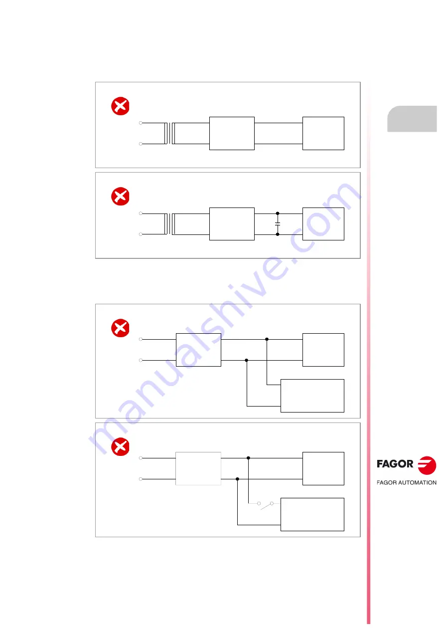
The following types of circuits should NOT be used.
1
Examples of circuits that cannot maintain the output voltage in an instantaneous
interruption (the output voltage drops under 20.4 V).
2
Examples of circuits that exceed the output voltage range (20.4 V to 28.8 V) due to load
fluctuations. For these circuits, use a regulated second phase to power devices with large
load fluctuations so as not to affect the CNC and other units.
Example 1. Not recommended diagram.
A rectifier circuit is a circuit that uses diodes for full wave rectification.
Example 2. Not recommended diagram.
A rectifier circuit is a circuit that uses diodes for full wave rectification.
Example 1. Not recommended diagram.
Example 2. Not recommended diagram.
AC input
CNC
Rectifier circuit
+
AC input
CNC
Rectifier circuit
AC input
CNC
Regulated
power supply
Device with large load
fluctuations.
AC input
CNC
Regulated
power supply
Device with high peak
currents due to load
(rush current).
Summary of Contents for CNC 8070
Page 1: ...Ref 1911 8070 CNC Hardware configuration...
Page 8: ...BLANK PAGE 8...
Page 14: ...BLANK PAGE 14...
Page 18: ...BLANK PAGE 18...
Page 22: ...BLANK PAGE 22...
Page 24: ...BLANK PAGE 24...
Page 26: ...BLANK PAGE 26...
Page 28: ...Hardware configuration CNC 8070 1 PREVIOUS INFORMATION 28 REF 1911...
Page 94: ...Hardware configuration CNC 8070 6 CENTRAL UNIT MONITOR Q7 A PLATFORM 94 REF 1911 C70 15AT...
Page 273: ...Hardware configuration CNC 8070 273 User notes REF 1911...
Page 274: ...Hardware configuration CNC 8070 274 User notes REF 1911...
Page 275: ...Hardware configuration CNC 8070 275 User notes REF 1911...


