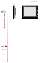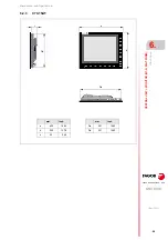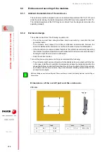
Hardware configuration.
CNC 8070
6.
CEN
T
RAL UNIT + MONITOR (Q7-A
PLATFORM).
Ha
rdware
function
ali
ty
(conne
ctors).
·108·
(R
EF
: 1911)
·A22·
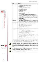
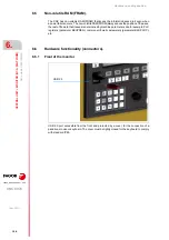
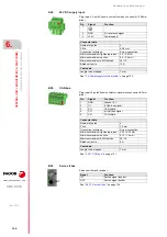
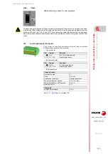
24 V DC supply input.
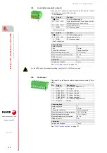
·B28· CAN
bus.
·B32· Sercos
II
bus.
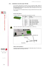
Connector data.
Number of poles.
3.
Pitch.
5,08 mm.
Connection technique.
Screw connection.
Minimum/maximum tightening torque. 0.5 / 0.6 Nm.
Minimum/maximum section.
0.2 / 2.5 mm².
Minimum/maximum AWG section.
24 / 12.
Rated current In.
12 A.
Cable data.
Length to be stripped.
7 mm.
"6.4 Power supply for the module."
Connector data.
Number of poles.
5.
Pitch.
3.5 mm.
Connection technique.
Screw connection.
Minimum/maximum tightening torque. 0.22 / 0.25 Nm.
Minimum/maximum section.
0.14 / 1.5 mm².
Minimum/maximum AWG section.
28 / 16.
Rated current In.
8 A.
Cable data.
Length to be stripped.
7 mm.
Plug-in part. 3-pole Phoenix-contact combicon connector (5.08 mm
pitch).
Pin
Signal.
Function.
1
- - -.
2
GND
0 V reference signal.
3
+24 V
Power supply.
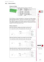
Plug-in part. 5-pole Phoenix-contact minicombicon connector (3.5 mm
pitch).
Pin.
Signal.
Function.
1
GND
Ground / 0 V.
2
CL
(LOW) bus signal.
3
SH
CAN shield.
4
CH
(HIGH) bus signal.
5
SH
CAN shield.
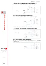
Sercos emitter and receiver.
Signal.
Function.
IN
Sercos signal receiver.
OUT
Sercos signal emitter.
IN
OUT
Summary of Contents for CNC 8070
Page 1: ...Ref 1911 8070 CNC Hardware configuration...
Page 8: ...BLANK PAGE 8...
Page 14: ...BLANK PAGE 14...
Page 18: ...BLANK PAGE 18...
Page 22: ...BLANK PAGE 22...
Page 24: ...BLANK PAGE 24...
Page 26: ...BLANK PAGE 26...
Page 28: ...Hardware configuration CNC 8070 1 PREVIOUS INFORMATION 28 REF 1911...
Page 94: ...Hardware configuration CNC 8070 6 CENTRAL UNIT MONITOR Q7 A PLATFORM 94 REF 1911 C70 15AT...
Page 273: ...Hardware configuration CNC 8070 273 User notes REF 1911...
Page 274: ...Hardware configuration CNC 8070 274 User notes REF 1911...
Page 275: ...Hardware configuration CNC 8070 275 User notes REF 1911...

