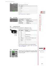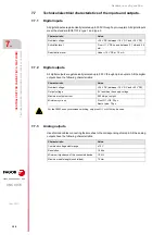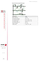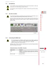
Hardware configuration.
CNC 8070
CENTRAL U
N
IT
FOR C
ABI
NET (Q7-A
PLATFORM).
7.
Ha
rdware
function
ali
ty
(conne
ctors).
·153·
(R
EF
: 1911)
·I24·
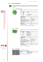
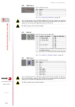
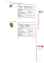
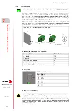
Local digital outputs (8 outputs).
Connector data.
Number of poles.
6.
Pitch.
2.5 mm.
Connection technique.
Spring connection.
Minimum/maximum section.
0.14 / 0.5 mm².
Minimum/maximum AWG section.
26 / 20.
Rated current In.
4 A.
Cable data.
Length to be stripped.
8 mm.
Left connector.
Pin 1 coded.
Right connector.
Pin 6 coded.
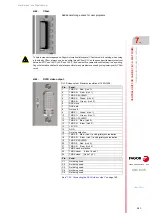
Plug-in part. Two coded connectors. 6-pole Phoenix-contact
minicombicon connector (2.5 mm pitch).
• Left connector. Pin 1 coded.
• Right connector. Pin 6 coded.
• Both connectors.
Pin.
Signal.
Function.
1
24 V
24 V DC voltage supply.
2-3
LO1 - LO2
Local digital outputs. In the laser model, use
these pins for PWM and synchronous
switching.
4-5
LO3 - LO4
Local digital outputs.
6
GND
0 V reference signal.
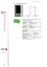
Pin.
Signal.
Function.
1
24 V
24 V DC voltage supply.
2- 5
LO5 - LO8
Local digital outputs.
6
GND
0 V reference signal.
The PWM and synchronized switching options can only use pin 2 (LO1) and pin 3 (LO2) on the left
connector.
Summary of Contents for CNC 8070
Page 1: ...Ref 1911 8070 CNC Hardware configuration...
Page 8: ...BLANK PAGE 8...
Page 14: ...BLANK PAGE 14...
Page 18: ...BLANK PAGE 18...
Page 22: ...BLANK PAGE 22...
Page 24: ...BLANK PAGE 24...
Page 26: ...BLANK PAGE 26...
Page 28: ...Hardware configuration CNC 8070 1 PREVIOUS INFORMATION 28 REF 1911...
Page 94: ...Hardware configuration CNC 8070 6 CENTRAL UNIT MONITOR Q7 A PLATFORM 94 REF 1911 C70 15AT...
Page 273: ...Hardware configuration CNC 8070 273 User notes REF 1911...
Page 274: ...Hardware configuration CNC 8070 274 User notes REF 1911...
Page 275: ...Hardware configuration CNC 8070 275 User notes REF 1911...

