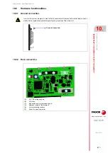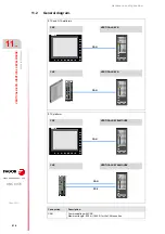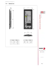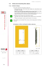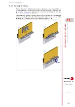
Hardware configuration.
CNC 8070
11.
VERTICAL KEYB
/ VE
RTICAL
KEYB+MOUSE.
Hardw
are fu
ncti
ona
lities.
·224·
(R
EF
: 1911)
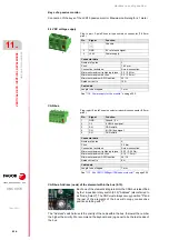
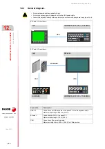
Keys of a passive monitor.
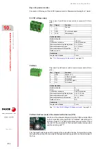
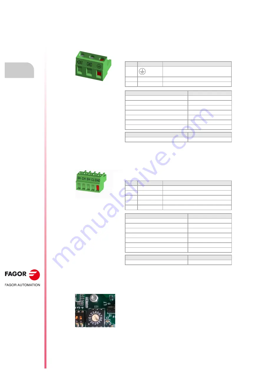
Connection of the keys of the LCD15 passive monitor. Maximum cable length is 1 meter.
24 V DC voltage supply.
CAN bus.
CAN bus. Address (node) of the element within the bus (0-15).
The "Address" switch also sets the priority of the node within the bus; the lower the number
the higher the priority. We recommend the keyboard and jog panel to be the last nodes of
the bus.
Connector data.
Number of poles.
3.
Pitch.
7.62 mm.
Connection technique.
Screw connection.
Minimum/maximum tightening torque. 0.5 / 0.6 Nm.
Minimum/maximum section.
0.2 / 2.5 mm².
Minimum/maximum AWG section.
24 / 12.
Rated current In.
12 A.
Cable data.
Length to be stripped.
7 mm.
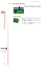
"11.5 Power supply for the module."
Connector data.
Number of poles.
5.
Pitch.
3.5 mm.
Connection technique.
Screw connection.
Minimum/maximum tightening torque. 0.22 / 0.25 Nm.
Minimum/maximum section.
0.14 / 1.5 mm².
Minimum/maximum AWG section.
28 / 16.
Rated current In.
8 A.
Cable data.
Length to be stripped.
7 mm.
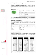
"11.7 Bus CAN (CANfagor/CANopen protocols)."
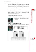
Each one of the elements integrated into the CAN bus is identified
by the 16-position rotary switch (0-15) "Address" (also referred to
as "Node_Select"). The CNC must always occupy position "0" and
the rest of the elements of the bus will occupy consecutive
positions starting with "1".
Plug-in part. 3-pole Phoenix-type combicon connector (7.62 mm
pitch).
Pin
Signal.
Function.
1
Chassis.
2
GND
0 V reference signal.
3
+24 V
Power supply.
1
Plug-in part. 5-pole Phoenix-contact minicombicon connector (3.5 mm
pitch).
Pin.
Signal.
Function.
1
GND
Ground / 0 V.
2
CL
(LOW) bus signal.
3
SH
CAN shield.
4
CH
(HIGH) bus signal.
5
SH
CAN shield.
Summary of Contents for CNC 8070
Page 1: ...Ref 1911 8070 CNC Hardware configuration...
Page 8: ...BLANK PAGE 8...
Page 14: ...BLANK PAGE 14...
Page 18: ...BLANK PAGE 18...
Page 22: ...BLANK PAGE 22...
Page 24: ...BLANK PAGE 24...
Page 26: ...BLANK PAGE 26...
Page 28: ...Hardware configuration CNC 8070 1 PREVIOUS INFORMATION 28 REF 1911...
Page 94: ...Hardware configuration CNC 8070 6 CENTRAL UNIT MONITOR Q7 A PLATFORM 94 REF 1911 C70 15AT...
Page 273: ...Hardware configuration CNC 8070 273 User notes REF 1911...
Page 274: ...Hardware configuration CNC 8070 274 User notes REF 1911...
Page 275: ...Hardware configuration CNC 8070 275 User notes REF 1911...


