Hardware configuration.
CNC 8070
OP-PANEL /
OP-PANEL+SPDL R
A
TE.
13.
Han
dwhe
el conne
cti
on.
·249·
(R
EF
: 1911)
13.7
Handwheel connection.
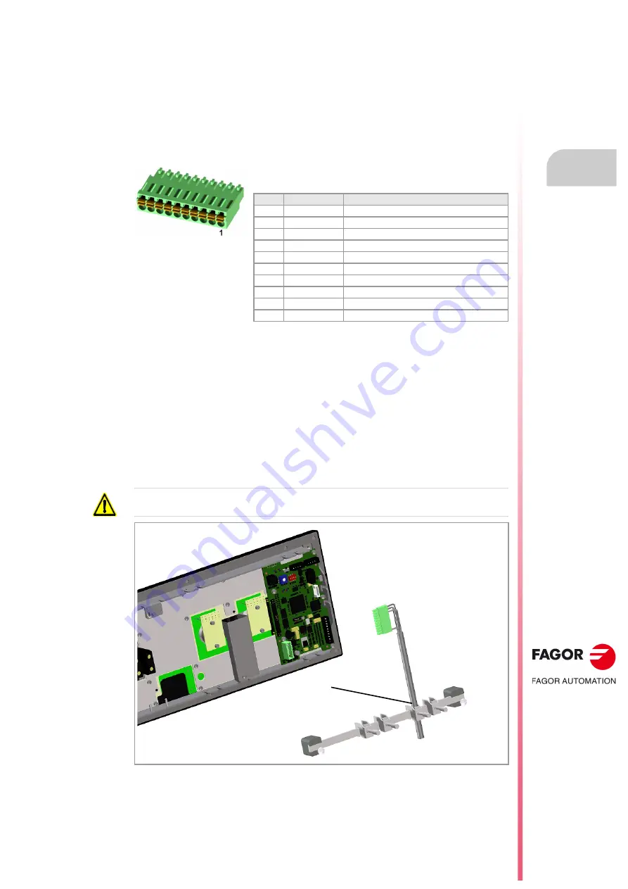
The keyboard admits the connection of up to 3 handwheels (MPG1, MPG2 and MPG3) with
A and B signals (5 V DC TTL). If he handwheel has an axis selector button, the button signal
may be connected to a digital input and may be managed from the PLC using the
NEXTMPGAXIS mark.
Connector pinout.
Cable characteristics.
The cable being used must have overall shield. The unshielded portion of the wires of an
unshielded cable cannot be longer than 75 mm.
Connection.
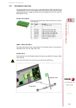
We recommend to run the handwheel cable as far away as possible from the power cables
of the machine.
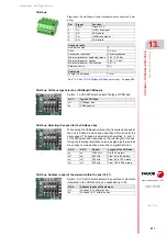
Plug-in part. 10-pole Phoenix-contact minicombicon connector
(3.5 mm pitch).
Pin.
Signal.
Function.
1
+5 V
5 V DC voltage supply.
2
- - -
- - -
3
- - -
- - -
4
MPG3-B
B signal of the third handwheel.
5
MPG3-A
A signal of the third handwheel.
6
MPG2-B
B signal of the second handwheel.
7
MPG2-A
A signal of the second handwheel.
8
MPG1-B
B signal of the first handwheel.
9
MPG1-A
A signal of the first handwheel.
10
GND
Power supply.
Always connect the shield of the cable to the ground plate using a metallic clamp.
Ground plate.
Cable shield.
Handwheel cable.
Summary of Contents for CNC 8070
Page 1: ...Ref 1911 8070 CNC Hardware configuration...
Page 8: ...BLANK PAGE 8...
Page 14: ...BLANK PAGE 14...
Page 18: ...BLANK PAGE 18...
Page 22: ...BLANK PAGE 22...
Page 24: ...BLANK PAGE 24...
Page 26: ...BLANK PAGE 26...
Page 28: ...Hardware configuration CNC 8070 1 PREVIOUS INFORMATION 28 REF 1911...
Page 94: ...Hardware configuration CNC 8070 6 CENTRAL UNIT MONITOR Q7 A PLATFORM 94 REF 1911 C70 15AT...
Page 273: ...Hardware configuration CNC 8070 273 User notes REF 1911...
Page 274: ...Hardware configuration CNC 8070 274 User notes REF 1911...
Page 275: ...Hardware configuration CNC 8070 275 User notes REF 1911...


