Hardware configuration.
CNC 8070
CONFIGURATION.
2.
Gene
ra
l diag
ram (ET
X
pl
atfo
rm).
·35·
(R
EF
: 1911)
2.13
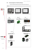
General diagram (ETX platform).
See the schematic description of all the elements that make up the CNC system:
CAN
CNC
Operator panel.
Remote modules.
Servo drive system.
RCS-S Modules.
Sercos II
DDS
VGA
Keyboard.
C70-10K
Sercos II
HORIZONTAL KEYB 2.0 + TOUCHPAD.
RCS-S
RIOW
RIO5
RIOR
CAN
C70-15
OP-PANEL
OP-PANEL+SPDL RATE
Keyboards.
HORIZONTAL KEYB
HORIZONTAL KEYB+MOUSE
VERTICAL KEYB
VERTICAL KEYB+MOUSE
CAN
U70
C70-15AT
MONITOR-21W-MULTITOUCH
Monitor.
USB
Summary of Contents for CNC 8070
Page 1: ...Ref 1911 8070 CNC Hardware configuration...
Page 8: ...BLANK PAGE 8...
Page 14: ...BLANK PAGE 14...
Page 18: ...BLANK PAGE 18...
Page 22: ...BLANK PAGE 22...
Page 24: ...BLANK PAGE 24...
Page 26: ...BLANK PAGE 26...
Page 28: ...Hardware configuration CNC 8070 1 PREVIOUS INFORMATION 28 REF 1911...
Page 94: ...Hardware configuration CNC 8070 6 CENTRAL UNIT MONITOR Q7 A PLATFORM 94 REF 1911 C70 15AT...
Page 273: ...Hardware configuration CNC 8070 273 User notes REF 1911...
Page 274: ...Hardware configuration CNC 8070 274 User notes REF 1911...
Page 275: ...Hardware configuration CNC 8070 275 User notes REF 1911...


