Hardware configuration.
CNC 8070
5.
CENTRAL
UNIT + MONITO
R (ETX PLATFORM).
Ha
rd
ware function
ality.
Co
nne
ctors.
·66·
(R
EF
: 1911)
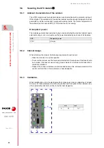
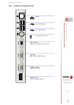
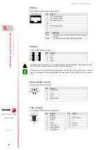
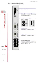
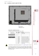
Ethernet.
8-pin RJ45 connector and 2 status LED's.
USB ports.
Type A USB double connector.
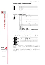
Mouse with PS-2 connector.
6-pin minidin female connector.
·VGA· connector.
15-pin female SUB-D HD type connector.
1
3
2
4 5
7
6
8
Pin.
Signal.
1
TX+ (transmit data).
2
TX- (transmit data).
3
RX+ (receive data).
4
- - -
5
- - -
6
RX- (receive data).
7
- - -
8
- - -
LED.
Meaning.
Green
The LED turns on when the central unit is connected to
network.
Yellow
The LED blinks when data is being transferred.
Pin.
Signal.
1
+ 5 V
2
DT -
3
DT +
4
GND
4
2
3
1
4
2
3
1
No USB devices must be used nor connected while executing a part program. Using USB devices may
slow down the execution or cause some "RT-IT overflow" type error.
USB devices must comply with the generic regulation IEC 61000-6-2:2005 on immunity for industrial
use. We recommend to also comply with the European Directive 2004/108/EC on EMC for industrial
use.
i
Pin.
Signal.
1
Mouse data.
2
- - -
3
GND
4
+5 V
5
Mouse clock.
6
- - -
1
3
5
2
4
6
Pin.
Signal.
1
MAINS
2
GREEN
3
BLUE
4
- - -
5
GND
6
GND_RED
7
GND_GREEN
8
GND_BLUE
Pin.
Signal.
9
- - -
10
GND_SYNC
11
- - -
12
- - -
13
HSYNC
14
VSYNC
15
- - -
5
1
10
6
15
11
Summary of Contents for CNC 8070
Page 1: ...Ref 1911 8070 CNC Hardware configuration...
Page 8: ...BLANK PAGE 8...
Page 14: ...BLANK PAGE 14...
Page 18: ...BLANK PAGE 18...
Page 22: ...BLANK PAGE 22...
Page 24: ...BLANK PAGE 24...
Page 26: ...BLANK PAGE 26...
Page 28: ...Hardware configuration CNC 8070 1 PREVIOUS INFORMATION 28 REF 1911...
Page 94: ...Hardware configuration CNC 8070 6 CENTRAL UNIT MONITOR Q7 A PLATFORM 94 REF 1911 C70 15AT...
Page 273: ...Hardware configuration CNC 8070 273 User notes REF 1911...
Page 274: ...Hardware configuration CNC 8070 274 User notes REF 1911...
Page 275: ...Hardware configuration CNC 8070 275 User notes REF 1911...


