Hardware configuration.
CNC 8070
EMERGENCY
BATTERY (ONLY ETX PLATFORM).
15.
Conn
ectors a
nd
conne
cti
on.
·257·
(R
EF
: 1911)
15.2
Connectors and connection.
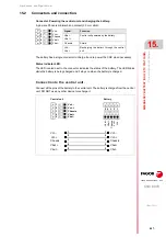
Connector. Powering the central unit and charging the battery.
5-pin male Phoenix minicombicon contact (3.5 mm pitch).
The battery has a single connector to charge it and to power the CNC when necessary.
Status indicator LED.
The LED located next to the connector indicates the status of the battery. The LED blinks
while the battery is being charged and it stays on when the battery is charged.
Connection to the central unit.
Connect all the pins of the battery to the central unit. The battery is charged from the central
unit; DO NOT use any other device to recharge it.
5
4
3
2
1
Vbat -
Vbat +
Chassis
Vch +
Vch -
Signal
Function
Vbat -
Vbat +
Central unit powered by the battery.
Chassis
Shield.
Vch -
Vch +
Recharging the battery through the central
unit.
Vch -
Vbat +
Vbat -
Chassis
Vch +
Vch -
Vbat +
Vbat -
Chassis
Vch +
1
2
3
4
5
1
2
3
4
5
5
4
3
2
1
Vbat -
Vbat +
Chassis
Vch +
Vch -
5 4 3 2 1
Vb
at
-
Vb
at
+
Ch
a
ss
is
Vc
h +
Vc
h -
Central unit
Battery
Summary of Contents for CNC 8070
Page 1: ...Ref 1911 8070 CNC Hardware configuration...
Page 8: ...BLANK PAGE 8...
Page 14: ...BLANK PAGE 14...
Page 18: ...BLANK PAGE 18...
Page 22: ...BLANK PAGE 22...
Page 24: ...BLANK PAGE 24...
Page 26: ...BLANK PAGE 26...
Page 28: ...Hardware configuration CNC 8070 1 PREVIOUS INFORMATION 28 REF 1911...
Page 94: ...Hardware configuration CNC 8070 6 CENTRAL UNIT MONITOR Q7 A PLATFORM 94 REF 1911 C70 15AT...
Page 273: ...Hardware configuration CNC 8070 273 User notes REF 1911...
Page 274: ...Hardware configuration CNC 8070 274 User notes REF 1911...
Page 275: ...Hardware configuration CNC 8070 275 User notes REF 1911...

