Hardware configuration.
CNC 8070
CENTRAL
UNIT + MONITO
R (ETX PLATFORM).
5.
Conn
ecti
ons.
·89·
(R
EF
: 1911)
5.12.7 Sercos II bus.
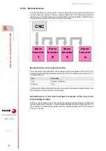
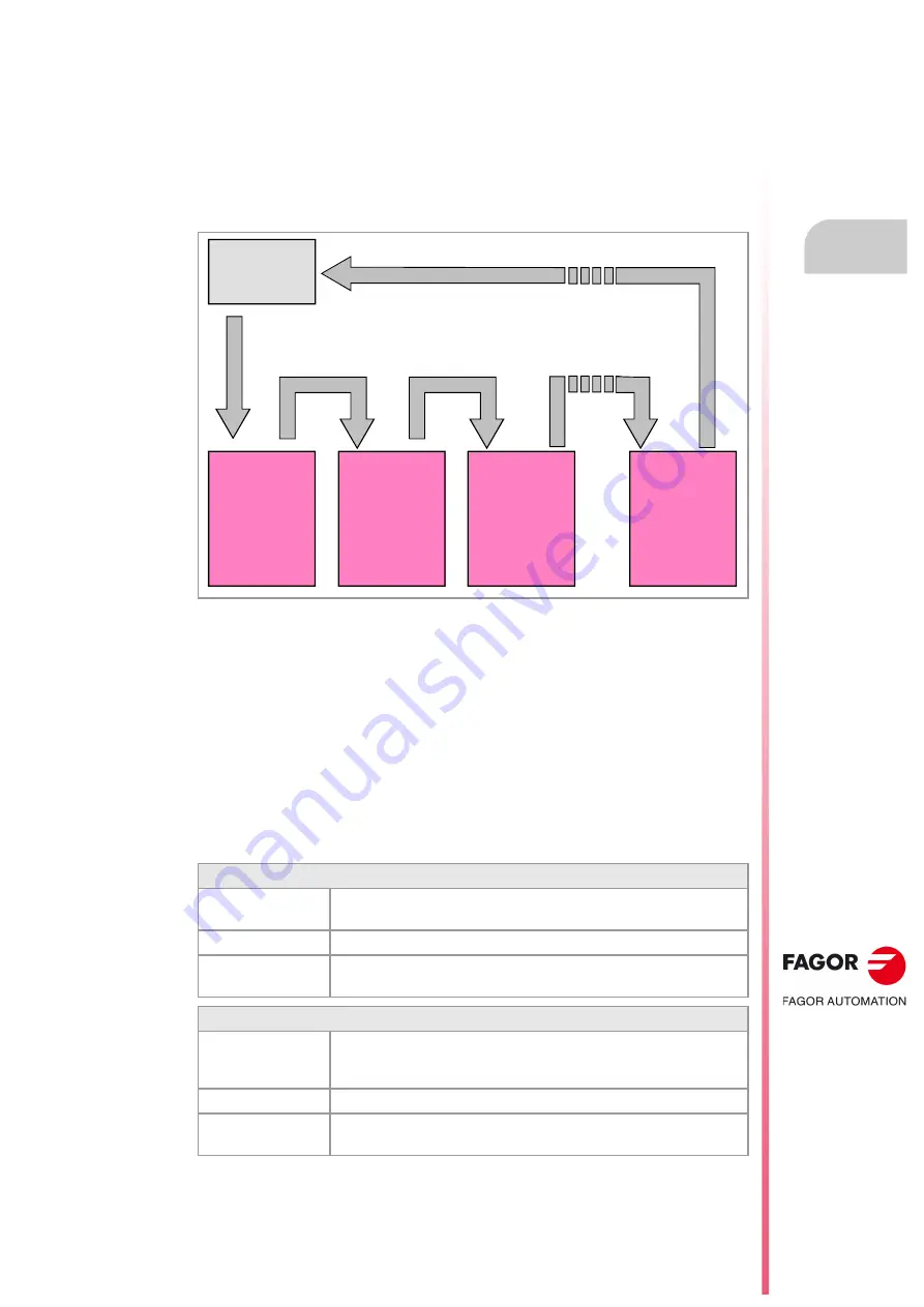
The Sercos interface is a communications standard especially designed for the machine-
tool industry offering a simple interface between the CNC and the drives. All the data and
commands are transmitted in digital format through fiber optic lines that make up a ring (the
Sercos ring) that connects all the elements of the bus (CNC and drives) to each other. Using
the Sercos interface considerably minimizes the necessary hardware, makes cabling
simpler and grants greater reliability to the system making it immune to electrical interference
(noise).
Sercos cable characteristics.
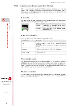
Fagor Automation provides the fiber optic cables needed for Sercos communication. There
are different types of cables depending on length and dynamic and static installation
characteristics.
• Fiber optic cable with polymer core (SFO, SFO-FLEX) for up to 40 meters. If the fiber
optic cable is going to withstand dynamic conditions (moving), always use the SFO-FLEX
cable If the cable will be subject to static conditions (it will not be moving), the SFO cable
will be enough.
• Fiber optic cable with glass core (SFO-V-FLEX) for over 40 meters.
Mechanical characteristics of the cables.
SFO cable.
Flexibility.
Normal. Minimum bending radius of 30 mm.
Only to be used when the cable will not be moving (static conditions).
Covering.
PUR. Polyurethane resistant to chemical used on machines.
Temperature.
Work: -20 ºC / 80 ºC (-4 ºF / 176 ºF).
Storage: -35 ºC / 85 ºC (-31 ºF / 158 ºF).
SFO-FLEX cable.
Flexibility.
High. Minimum static bending radius of 50 mm and a dynamic radius of 70
mm.
Special cables to be used in cable carrying chains.
Covering.
PUR. Polyurethane resistant to chemical used on machines.
Temperature.
Work: -20 ºC / 70 ºC (-4 ºF / 158 ºF).
Storage: -40 ºC / 80 ºC (-40 ºF / 176 ºF).
CNC
DRIVE
1
DRIVE
2
DRIVE
3
DRIVE
n
Summary of Contents for CNC 8070
Page 1: ...Ref 1911 8070 CNC Hardware configuration...
Page 8: ...BLANK PAGE 8...
Page 14: ...BLANK PAGE 14...
Page 18: ...BLANK PAGE 18...
Page 22: ...BLANK PAGE 22...
Page 24: ...BLANK PAGE 24...
Page 26: ...BLANK PAGE 26...
Page 28: ...Hardware configuration CNC 8070 1 PREVIOUS INFORMATION 28 REF 1911...
Page 94: ...Hardware configuration CNC 8070 6 CENTRAL UNIT MONITOR Q7 A PLATFORM 94 REF 1911 C70 15AT...
Page 273: ...Hardware configuration CNC 8070 273 User notes REF 1911...
Page 274: ...Hardware configuration CNC 8070 274 User notes REF 1911...
Page 275: ...Hardware configuration CNC 8070 275 User notes REF 1911...

