DC Servo Drive System Manual Ver: 0009
DC - 11/32
2.3
CONNECTORS
Power Terminals
Motor Output: ±150 Vdc output voltage applied to the motor
Output current to the motor (continuous/peak for 4.5 seconds):
DCS-08:
8A/16A
DCS-14:
14A/28A
Maximum current with PWM on a carrier frequency of 10 kHz.
Watch out for polarity. See page 23.
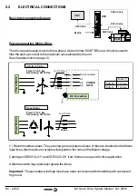
Power Input: 94-120Vac three-phase supply through a transformer. See page 22.
The maximum cable section at these power terminals is: 2.5 mm
2
.
Total isolation between power and control circuits.
Control Signals
±10V voltages, Pins 1,2,3: Internal power supply so the user can easily generate a velocity
command. It offers a maximum current of 20mA limited internally.
Velocity command. Pins 4,5,6:
Current command. Pins 4,7:
See page 25. The motor torque is directly proportional to the current. "Torque command".
Tacho feedback. Pins 8,9: Velocity feedback input from the tacho into the drive. Be careful with
the polarity. See page 24.
Monitoring. Pins 10,11,12: Voltage outputs for monitoring motor speed and current. Voltage
range of ±10V. See page 23.
Common, Pin 15: Reference point for the following Enable signals:
Drive Enable, Pin 14: At 0Vdc, disables current through the motor which loses its torque.
Speed Enable, Pin 13: A 0Vdc, forces a "zero speed" command.
These control signals are activated at +24Vdc.
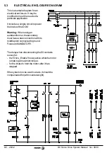
Drive OK. Pins 16,17: Relay contact that closes when the internal status of the drive is OK. It
must be included in the electrical maneuver. See page 26.
Encoder Input: Encoder signal input to the motor for velocity feedback.
Encoder Output: Encoder output for closing the loop at the CNC. See page 24.
The maximum section for these cables is 0.5 mm
2
.


