DC Servo Drive System Manual Ver: 0009
DC - 13/32
2.4
STATUS DISPLAY
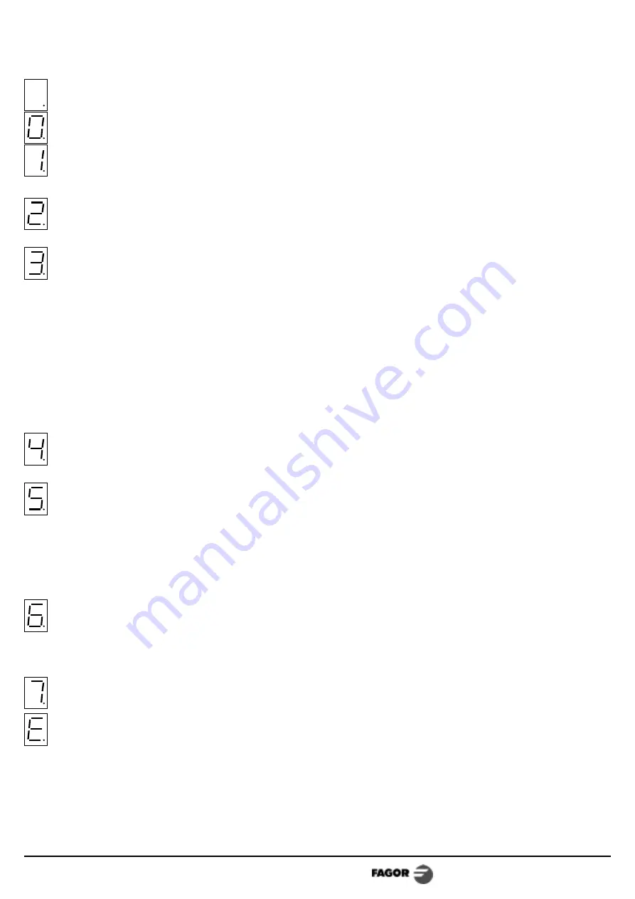
It is a 7-segment display for monitoring the Drive status.
The unit is under power, the "Drive Enable" pin is deactivated, (0 Volts at pin 14).
The motor has no torque.
"Speed Enable" off (0 Volts at pin 13), and "Drive Enable" (+24V at pin 14).
The motor has torque with no velocity command.
Everything is OK. "Drive Enable" and "Speed Enable" are active and the Motor responds to
the command.
Current leak from power lines to ground.
Solutions: carry out the motor maintenance procedures. Check the insulation of the power
cables.
No Feedback.
Solutions: Check that jumper J1 selects the feedback mode being used. Check that the
feedback cable and connectors are properly connected. Check that the winding circuit is not
open. When working in velocity command mode, make sure that jumper J4 is in the (bc)
position. When working in torque command mode, make sure that the RAPT resistor of the
identity module is short-circuited.
In the case of an Encoder, check the polarity of the voltage applied to the winding and that
the signal pairs (A,*A) and (B,*B) are not interchanged.
In the case of tacho feedback, check the polarity of the winding and that of the tacho. Check
that the tacho is not open or defective.
Drive overtemperature.
Solutions: Smooth the duty cycle. Improve its cooling. The unit will return to its normal running
status when it cools down below 78°C (172°F).
Motor overload. The I·T protection has gone off. In other words, the motor has maintained an
average current greater than the maximum allowed (Iomax
M
) for too long. The duty cycle is
too demanding for the capabilities of the motor. The motor is working beyond its rated
current.
Solutions: Smooth the duty cycle. Limit motor acceleration with ACC/DEC RAMPS. Limit the
commands, MAX.CURRENT LIMIT and MAX.SPEED. Decrease the RIT, thus allowing the
system to further force the motor.
Overcurrent. There has been an instantaneous current peak greater than the maximum allowed
according to the table on page 11.
Solutions: Limit motor acceleration with ACC/DEC RAMPS. If the motor has low inductance and
the current ripple is excessive, add an inductance in series with the winding circuit (this is
never required with Fagor DCM motors).
Overvoltage. For an instant, the internal Bus voltage has exceeded 193 V.
Solutions: The Ballast circuit may be defective or the supply voltage is too high.
Low-voltage. The supply voltage is too low.
Notes:
All the alarms except the 4. and E. are latched and the unit must be powered off and, after 30
seconds, turned back on.
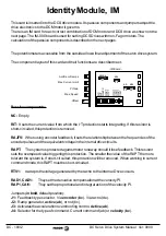
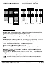
J1, J4, RAPT, ACC/DEC RAMPS, MAX.CURRENT LIMIT, MAX.SPEED and RIT are elements for
adjusting the servo drive system and they are described in the section on "the Identity Module IM".


