DC Servo Drive System Manual Ver: 0009
DC - 7/32
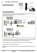
Includes terminals for:
Power input for the motor winding.
Input for electromechanical brake
Tacho voltage output.
Safety thermal contact
1.4
TERMINAL BOX
When the motor winding is supplied with the polarity indicated on the terminal box (B+, E-), the
rotor turns clockwise (CWR, clockwise rotation), as shown in the diagram. And, for this turning
direction, the tacho generates a voltage at its terminals (Tacho) also with the polarity indicated on
the box (+, -).
The electromechanical brake releases the motor shaft when applied 24 Vdc.
When stationary, it holds the motor shaft.
The thermal switch watches the armature temperature.
1.5
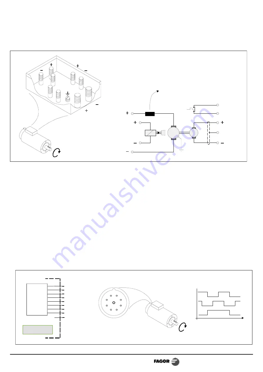
ENCODER OUTPUT CONNECTOR
Front View
TTL
En
code
r
DC Motor
9
8
7
6
5
4
3
2
1
6
5
4
3
2
1
7
8
9
B
A
Z
t
Clockwise Rotation (CWR)
signals:
CWR
Clockwise Rotation
+5V
*A
B
*B
Z
*Z
0V
A
Pin Signal
NC
E
B
Motor
Power
Tacho
Thermal
Brake
D
C
CWR
Clockwise Rotation
E
B
G
M
D
C
N.C.
Tacho
Brake
Thermal
Motor
Power
Ch.
Ch.
DC-IND-2/28 inductance
only needed with the motors
FXM 42.30A and 43.30A


